The Cisco Catalyst 9500 Series Switches support optional network modules for uplink ports on some of the configurations.
The default switch configuration does not include the network module. When you purchase the switch, you can choose from the network modules described in Tables2 and 3.
Table2. Network module numbers and descriptions
|
Network module |
Description |
|
|
Cisco Catalyst 9500 Series Network Module 8-port 1/10 Gigabit Ethernet with SFP/SFP+ |
|
|
Cisco Catalyst 9500 Series Network Module 2-port 40 Gigabit Ethernet with QSFP+ |
C9500-NM-8X: This module has eight 10G SFP module ports. Any combination of standard SFP modules are supported.
Note: This is supported on the following switch models: C9500-16X, C9500-40X
C9500-NM-2Q: This module has two 40G QSFP module ports. Any combination of standard QSFP modules are supported.
Note: This is supported on the following switch models: C9500-16X, C9500-16X, C9500-40X
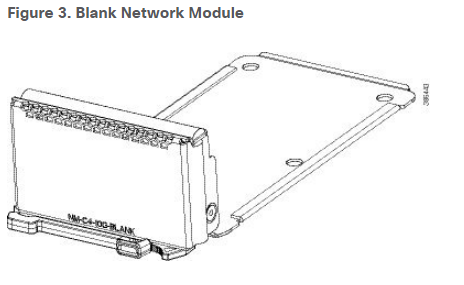
Blank Network Module (NM-C4-10G-BLANK): Insert this blank module when the switch has no uplink ports (this is required for sufficient air flow).
Table3. Network module matrix
|
Model |
C9500-NM-8X |
C9500-NM-2Q |
|
No |
No |
|
|
No |
No |
|
|
No |
No |
|
|
No |
No |
|
|
No |
No |
|
|
No |
No |
|
|
Yes |
Yes |
|
|
Yes |
Yes |
Figure1. C9500-NM-8X Network Module
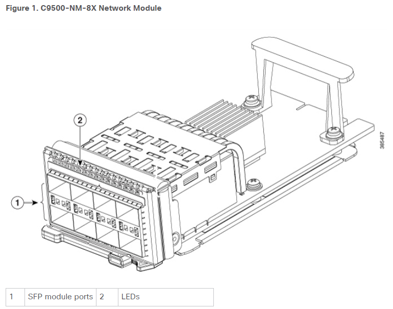
Figure2. C9500-NM-2Q Network Module
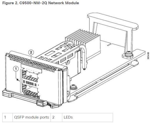
Figure3. Blank Network Module
Installing a Network Module in the Switch
Note: The switch can operate without a network module, but a blank module (with no ports or SFP slots) is available and should be installed when uplink ports are not required.
Note: The switch generates logs when you insert or remove a network module with SFP/SFP+/SFP28 slots.
Use only supported network modules and SFP, SFP+, SFP28 or QSFP modules. Each module has an internal serial EEPROM that is encoded with security information.
The network module is hot-swappable. If you remove a module, replace it with another network module or a blank module.
Note: The switch complies with EMC, safety, and thermal specifications when a network module is present. If no uplink ports are required, install a blank network module.
Before you begin
When installing network modules, observe these precautions:
- Do not remove the blank module from the slot unless you are installing an SFP, SFP+, SFP28 or QSFP module. Either a module or a dust plug must be in the slot at all times.
- Do not remove the dust plugs from the fiber-optic SFP, SFP+, SFP28 and QSFP modules or the rubber caps from the fiber-optic cable until you connect the cable. The plugs and caps protect the module ports and cables from contamination and ambient light.
- Removing and installing a network module can shorten its useful life. Do not remove and insert a network module more often than is necessary.
- To prevent ESD damage, follow your normal board and component handling procedures when connecting cables to the switch and other devices.
Procedure
Step1: Attach an ESD-preventive wrist strap to your wrist and to an earth ground surface.
Step2: Remove the module from the protective packaging.
Step3: Remove the blank module from the switch and save it.
Caution: Verify the correct orientation of your module before installing it. Incorrect installation can damage the module.
Caution: Do not install the network module with connected cables or installed SFP/SFP+/SFP28 modules. Always remove any cables and modules before you install the network module.
Caution: A module interface might become error-disabled when a network module with connected fiber-optic cables is installed or removed. If an interface is error-disabled, you can reenable the interface by using the shutdown and no shutdown interface configuration commands.
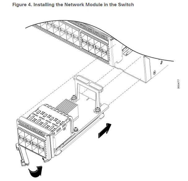
Step4: Position the module face up to install it in the module slot. Slide the module into the slot until the back of the module faceplate is flush with the switch faceplate. Secure the network module in place by latch.
Figure4. Installing the Network Module in the Switch
Removing a Network Module
Note: The switch complies with EMC, safety, and thermal specifications when a network module is present. If no uplink ports are required, install a blank network module.
Procedure
Step1: Attach an ESD-preventive wrist strap to your wrist and to an earth ground surface.
Caution: Do not remove the network module with connected cables or installed SFP/SFP+/SFP28/QSFP modules. Always remove any cables and modules before you remove the network module.
Caution: A module interface might become error-disabled when a network module with connected fiber-optic cables is installed or removed. If an interface is error-disabled, you can reenable the interface by using the shutdown and no shutdown interface configuration commands.
Step2: Disconnect the cables from the SFP/SFP+/SFP28/QSFP module.
Step3: Release latch and carefully slide the network module out of the slot.
Step4: Install a replacement network module or a blank module in the slot.
Step5: Place the module that you removed in an antistatic bag or other protective environment.
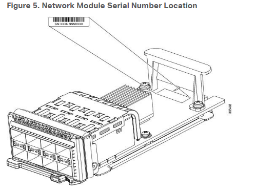
Finding the Network Module Serial Number
If you contact Cisco Technical Assistance regarding a network module, you need to know its serial number.
Figure5. Network Module Serial Number Location
Learn more: Catalyst 9500 Series Switches Install and Upgrade Guides
Cisco Catalyst 9500 Series configurations and port density
Table1. Cisco Catalyst 9500 Series configurations and port density
|
Model |
Description |
1G port density |
10G port density |
25G port density |
40G port density |
100G Port density |
10G port density with breakout cable |
25G port density with breakout cable |
|
Cisco Catalyst 9500 Series high-performance 32-port 100 Gigabit Ethernet switch with QSFP28 |
– |
– |
– |
32 (64) |
32 (64) |
96 |
96 |
|
|
Cisco Catalyst 9500 Series high-performance 32-port 40 Gigabit Ethernet switch with QSFP+ |
– |
– |
– |
32 (64) |
16 (32) |
- |
- |
|
|
Cisco Catalyst 9500 Series high-performance 48-port 1/10/25G Gigabit Ethernet switch with SFP28 |
48 (96) |
48 (96) |
48 (96) |
4 (8) |
4 (8) |
– |
– |
|
|
Cisco Catalyst 9500 Series high-performance 24-port 1/10/25G Gigabit Ethernet switch with SFP28 |
24 (48) |
24 (48) |
24 (48) |
4 (8) |
4 (8) |
– |
– |
|
|
Cisco Catalyst 9500 Series 24-port 40 Gigabit Ethernet switch with QSFP+ |
– |
– |
– |
24 (48) |
- |
96 |
– |
|
|
Cisco Catalyst 9500 Series 12-port 40 Gigabit Ethernet switch with QSFP+ |
– |
– |
– |
12 (24) |
- |
48 |
– |
|
|
Cisco Catalyst 9500 Series 40-port 1/10 Gigabit Ethernet Switch with SFP/SFP+ |
48 (96) |
48 (96) |
– |
2 (4) |
- |
8 |
– |
|
|
Cisco Catalyst 9500 Series 16-port 1/10 Gigabit Ethernet switch with SFP/SFP+ |
24 (48) |
24 (48) |
– |
2 (4) |
- |
8 |
– |
All numbers in the above table are for the standalone switch, except where indicated in parentheses () for StackWise Virtual:
** with uplink module.
More Related:
Why Migrate to Cisco Catalyst 9500 Switches?
Migration Guide: Cisco Catalyst 2960-X Series to New 9200 Series
Cisco’s New Intent-based Networking & New Line of Catalyst 9000 Switches
Mapping between Catalyst 3850, Catalyst 4500E/4500X, 6800 and Catalyst 9000
Switching for a Digital World with Catalyst 9000 Switches
Cisco Catalyst 9000 Family-Technical Deep Dive
How to Find Your Right New Catalyst 9000 Switches?
Why Migrate to the Cisco Catalyst 9200 Series Switches?
Why Migrate to Cisco Catalyst 9300 Switches?
Why Migrate to the Cisco Catalyst 9400 Series Switches?
More Resources:
[PDF] Cisco Catalyst 9500 Switch Datasheet
[PDF] Cisco Catalyst 9400 Series Line Cards Datasheet
[PDF] Cisco Catalyst 9300 Switch Datasheet
[PDF] Cisco Catalyst 9200 Switch Datasheet
Cisco Catalyst 9800 Series Wireless Controllers Data Sheet
Transition Guide
[PDF] Guide to Upgrade Cisco Access and Backbone Switch
[PDF] Selecting Cisco Switches-Campus, Branch, Digital Building
[PDF] Cisco Catalyst 4500/6500/6800 Series Transition Guide
[PDF] Migrating from Catalyst 3850, Catalyst 4500E/4500X, Catalyst 6800 to Catalyst 9000


