OLT Capacity Planning for GPON Access NetworksPlan OLT capacity for GPON OLT systems and EA5800 capacity planning, optimizing GPON split ratio and OLT uplink design for scalable fiber access.
Enterprise OLT Platform Selection for Fiber AccessDesign enterprise OLT platform strategy for GPON OLT platform, modular OLT chassis, and OLT service boards to scale passive optical LAN and XG-PON evolution.
Tunnel Video Surveillance VLAN Stability over FiberDesign stable tunnel video surveillance VLANs using optical transport backbone and Arista fiber aggregation for resilient Huawei OptiX OSN CCTV networks.
Fiber vs Copper in Industrial Networks Design GuideCompare fiber vs copper in industrial ethernet, plan hybrid industrial fiber network designs, and select rugged ethernet switches and industrial SFP transceivers.
Power over Ethernet (PoE) has become a cornerstone technology for modern enterprise networks, enabling a single Ethernet cable to deliver both data and electrical power to devices such as IP phones, wireless access points (WAPs), and IP cameras.
For network administrators and system integrators, understanding how to enable PoE on Cisco switch is essential to ensure devices receive reliable power while maintaining overall network efficiency and uptime. Proper planning and configuration reduce the risk of oversubscription and optimize switch utilization.
This guide provides a comprehensive overview of PoE standards, switch capabilities, deployment planning, CLI configuration, troubleshooting, and best practices tailored for Cisco Catalyst switches.
Part 1: PoE Standards and Capabilities
Cisco switches automatically detect powered devices (PDs) and allocate power based on IEEE standards or proprietary protocols such as Cisco UPOE. Key standards include:
Standard
Max Power per Port
Typical Devices
IEEE 802.3af (PoE)
15.4 W
Basic IP phones, cameras
IEEE 802.3at (PoE+)
30 W
HD cameras, Wi-Fi APs
IEEE 802.3bt (PoE++)
60–71 W
PTZ cameras, multi-radio WAPs
Cisco UPOE
60 W
High-power devices, multi-sensor cameras
Powered Device Detection: Cisco switches leverage CDP or LLDP to negotiate the required power. Non-CDP/LLDP devices may require manual configuration using power inline static or power inline consumption commands.
Diagram Suggestion: PoE port power flow – Detection → Classification → Negotiation → Power Allocation → Monitoring
Part 2: Planning Your PoE Deployment and Budget
Careful planning ensures reliable PoE delivery and optimal switch utilization.
Calculating Total PoE Budget
Device Requirements: Sum the maximum power of all connected devices.
Switch Capacity: Verify that total PD power does not exceed the switch PoE budget.
Safety Margin: Consider cable loss, future expansion, and redundancy.
Example Calculation: Six IP cameras at 8W each + two PTZ cameras at 20W each → Total = 88W. Choose a switch with ≥120W PoE budget.
Switch(config)# interface vlan 1
Switch(config-if)# ip address 192.168.1.10 255.255.255.0
Switch(config-if)# no shutdown
Switch(config)# ip default-gateway 192.168.1.1
Step 4: Enable PoE on Interfaces
Single or Range of Ports:
Switch(config)# interface range GigabitEthernet1/0/11-20
Switch(config-if-range)# description PoE_Ports
Switch(config-if-range)# power inline auto
Switch(config-if-range)# no shutdown
Optional Settings:
power inline auto max
power inline static max
power inline never
Step 5: Verify and Save Configuration
Switch# show power inline
Switch# show interface status
Switch# write memory
Tip: Insert CLI screenshot for guidance.
Part 4: Advanced PoE Management, Troubleshooting, and Best Practices
Even after enabling PoE, administrators should monitor, optimize, and prevent common issues.
Common Pitfalls
Oversubscribed Power: Monitor with show power inline.
Non-CDP/LLDP Devices: Manually configure power if required >15.4W.
Disabled Policing: Keep power inline police enabled.
Protocol Conflicts: Avoid running CDP and LLDP simultaneously on the same port.
Practical Deployment Tips
Topology Planning: Centralize power, use StackPower or redundant PoE supplies.
Remote Management: Use SSH for secure CLI access.
VLAN Segmentation: Separate voice, video, and data traffic.
Security: Strong passwords, ACLs, port security.
Monitoring: Regularly check show power inline and syslog events.
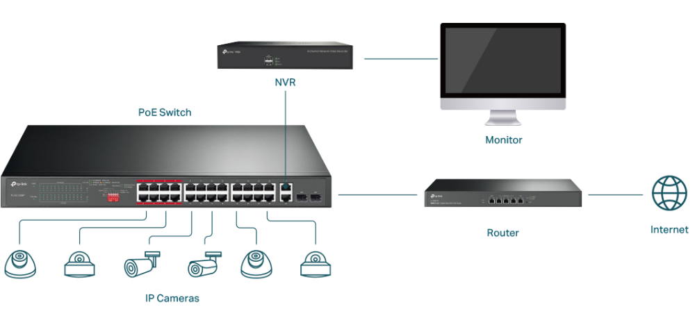
Diagram Suggestion: Enterprise PoE topology with IP cameras, APs, and phones connected to a Catalyst PoE switch, including power budget annotations.
Part 5: PoE Budget Examples
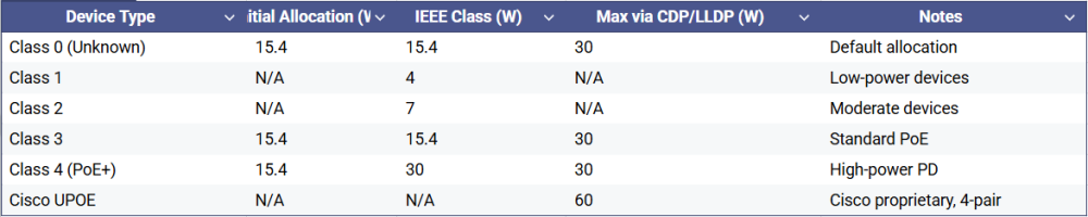
Conceptual PoE Budget Table
Key Note: Always account for cable losses and power overhead when manually configuring maximum port power.
Part 7: Security and Network Isolation Recommendations
Use VLANs to segregate IP cameras, phones, and data devices
Enable QoS to prioritize video streams
Consider port isolation for sensitive devices
Dual NIC NVRs can separate video traffic for enhanced security
Part 8: FAQ
Q1: How to activate PoE switch?
Cisco PoE switches usually have PoE enabled by default in auto mode. Simply connect a powered device (PD) such as an IP phone, wireless AP, or IP camera to a PoE-capable port, and the switch will automatically detect and provide power if budget allows.
To manually configure: enable → configure terminal
Enter interface: interface gigabitethernet1/0/x
Configure PoE mode:
Auto: power inline auto
Static: power inline static max
Disable: power inline never
Save: copy running-config startup-config
Q2: How to check if PoE is enabled on port Cisco?
Use these CLI commands: show power inline → Displays PoE status and consumption for all ports.
show power inline interface → Detailed per-port PoE info.
show interface status → Confirms port operational status.
If status shows auto or power allocation in watts, PoE is enabled.
Q3: How to enable PoE in Cisco 2960?
On Cisco Catalyst 2960 series, PoE is enabled by default on PoE-capable ports. For devices requiring PoE+ (802.3at) or higher than 15.4W without CDP/LLDP negotiation, configure manually:
enable
configure terminal
interface gigabitethernet1/0/1
power inline static max 25000
end
copy running-config startup-config
This ensures up to 25W delivery for non-CDP/LLDP devices.
Q4: How to check if a PoE switch is working or not?
Connect a PoE device and check if it powers on.
Use CLI:
show power inline → Verify port is delivering power.
show interface status → Check if port is up.
Observe device behavior (e.g., IP phone boots, AP broadcasts SSID).
Check port LEDs and system logs for PoE errors or power policing events.
Part 9: Conclusion
Mastering how to enable PoE on Cisco switch ensures reliable, scalable, and secure power delivery. Planning PoE budgets, choosing appropriate Cisco PoE switches, configuring ports correctly, and monitoring consumption are critical for enterprise-grade deployments.
Next Steps: Review Cisco PoE switch pricing and availability, and consult official documentation or certified network professionals for mission-critical deployments.
Expertise Builds Trust
20+ Years • 200+ Countries • 21500+ Customers/Projects CCIE · JNCIE · NSE7 · ACDX · HPE Master ASE · Dell Server/AI Expert