Fortifying Your Network: A Comprehensive Guide to Cisco Switch Power Redundancy Setup
Selene Gong
In today's interconnected world, network downtime can translate directly into significant financial losses and reputational damage. For network engineers, IT managers, and system integrators, ensuring high availability (HA) and business continuity is paramount. A critical component of a resilient network infrastructure is a robust Cisco switch power redundancy setup. This guide covers everything from fundamental concepts and configuration steps to best practices, practical examples, PoE budget planning, and buying advice to help you optimize your network power strategy.
Part 1: What is Cisco Switch Power Redundancy? Understanding PSU and StackPower Options
To implement a reliable Cisco switch power redundancy setup, it is crucial to understand the different types of power redundancy available. Cisco offers multiple approaches, including redundant power supplies (PSUs) within individual switches, StackPower technology for Catalyst 9300 stacks, and external Redundant Power Systems (RPS/XPS) for standalone switches. Knowing how these options differ ensures you can plan an optimal redundancy strategy that maximizes uptime and minimizes service interruptions.
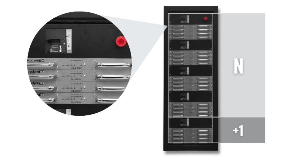
Part 2: N+1 Power Supply Unit (PSU) Explained
N+1 redundancy is a common strategy where N represents the number of power supplies required to run the system, and +1 signifies an additional PSU that can take over if one active unit fails. For Catalyst 9400 and 9600 Series switches, you can configure redundant N+1 mode, reserving one PSU specifically for backup. The default standby PSU slot is PS8 in this mode.
Understanding N+1 redundancy sets the foundation for dual PSU deployment and more advanced solutions like StackPower, which extends redundancy across multiple switches in a stack.
Part 3: Redundant Power Supplies for Individual Switches
Redundant power supplies provide high availability for individual switches and form the foundation of a robust Cisco switch power redundancy setup. Installing multiple PSUs within a single chassis ensures continuous operation in case of failure, and different operating modes allow flexibility depending on your power needs.
Combined Mode: All installed PSUs share the load and operate up to 100% capacity. For example, adding a second PSU to a Catalyst 9300 can increase the total PoE budget, supporting more endpoints.
Redundant Mode (1:1 or N+N): One or more PSUs are reserved to take over in case of failure, ensuring uninterrupted operation.
Optimizing PSU placement and load sharing within the chassis prevents service disruption and prepares the network for stack-level redundancy with StackPower.
Part 4: Cisco StackPower Technology for Catalyst 9300 Switches
For environments using stackable Catalyst 9300 switches, StackPower introduces an innovative approach to power redundancy. Unlike traditional dual PSU setups that only protect a single switch, StackPower aggregates all available power from the stack into a shared pool. This allows dynamic redistribution during PSU failures, improving uptime and overall efficiency.
Power Sharing Mode (Default): All input power is pooled without reserving a backup.
Redundant Mode: Reserves power equal to the largest PSU to provide immediate backup.
Zero-Footprint RPS: Eliminates the need for a separate external RPS, leveraging the stack's internal power pool.
StackPower enhances PoE distribution and ensures critical endpoints remain powered even during power fluctuations. It is especially useful for high-density deployments where every watt counts.
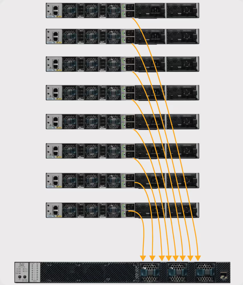
Part 5: Cisco Redundant Power System (RPS) and Expandable Power System (XPS 2200)
For networks with multiple standalone switches, external power solutions complement internal redundancy. RPS 2300 provides 1:N redundancy for multiple switches, while XPS 2200 supports up to eight Catalyst 9300 switches in a star topology. Understanding these options helps in designing a dual PSU or StackPower setup that fits your network's scale and redundancy requirements.
Integrating RPS/XPS solutions with internal PSUs ensures continuous operation across both standalone and stacked environments, forming a comprehensive Cisco switch power redundancy setup.
Part 6: Step-by-Step Guide to Cisco Switch Power Redundancy Setup
With the concepts clear, practical setup ensures your switches remain operational during power events. The following steps cover both chassis-based and stackable Cisco switches.
1. Physical Installation of Power Supplies
Identify PSU slots on your switch chassis.
Insert PSUs until fully seated.
Connect appropriate AC/DC power cords.
Check PSU LEDs (Green = Good; Amber/Red = Issue).
StackPower Tip: Install at least one PSU in all switches before adding additional units to a single switch to balance the stack’s power.
2. Configuring Power Redundancy Modes via CLI
Catalyst 9400/9600 Series Switches:
Combined Mode (Default): Switch(config)# power redundancy-mode switch 1 combined
Reliable sourcing ensures warranties, fast delivery, and technical support. Trusted vendors like router-switch (website) are recommended for enterprise deployments.
Part 11: Conclusion: Ensuring High Availability with Cisco Switch Power Redundancy Setup
Implementing a robust Cisco switch power redundancy setup safeguards your network against power failures. From dual PSU deployment to StackPower and external RPS/XPS systems, proper planning, monitoring, and testing are critical to maintaining business continuity. Regularly verifying configurations and testing failover mechanisms ensures uninterrupted network operation and PoE delivery to critical devices.
Part 12: FAQ: Cisco Switch Power Redundancy Setup Questions
Q1: How do I configure power redundancy on a Cisco 9300 switch?
A1: Use Cisco StackPower technology. Default mode is Power-sharing, pooling all power. Redundant mode reserves the largest PSU for backup. Configure strict/non-strict modes for load control.
Q2: What is Cisco StackPower and how is it different from RPS?
A2: StackPower aggregates PSU power across a stack for 1+N redundancy. RPS uses 1:N redundancy for standalone switches, with potential delay during failover.
Q3: Which Cisco switches support dual PSU redundancy?
A3: Catalyst 6500, 9300, 9400, 9500, 9600 series. StackPower allows shared power across 9300 stacks.
Q4: Can Catalyst switch PSUs be hot-swapped?
A4: Yes, Catalyst 9000 series PSUs support online insertion and removal (OIR). Remove PSU, wait a few minutes, and re-insert while the switch remains powered.