
















































































The Cisco N9K-C93180YC-FX3 is commonly deployed in data-center leaf, aggregation, and high-density server-connectivity designs. When two switches are used as a vPC pair, the result depends on more than connecting two cables between them. The peer-link, peer-keepalive, LACP, VLANs, MTU, optics, and consistency parameters all need to be planned together.
This guide assumes that the switches run Cisco NX-OS in standalone mode. Cisco ACI uses a different management and policy model, so its configuration should not be copied directly from this workflow.
What vPC Does in a Two-Switch Design
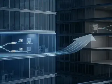
A vPC allows two Cisco Nexus switches to present themselves as one logical Layer 2 device to a connected server, switch, firewall, or other device that supports link aggregation.
Instead of connecting both downstream links to one physical switch, a dual-homed device can form one LACP port channel across both Nexus peers. This allows both links to participate in forwarding and provides a path for continued connectivity when one link or one peer fails.
- Two physical Nexus switches operate as one vPC domain.
- A downstream device can use an active-active port-channel across both peers.
- Available uplink bandwidth can be used instead of leaving one link blocked by STP.
- Link or peer failures can be handled without relying only on STP convergence.
The peer-link and peer-keepalive do different jobs. The peer-link carries synchronization and required inter-peer traffic. The peer-keepalive path helps the peers determine whether the other switch is still alive.
FX3 Hardware and Design Scope
The N9K-C93180YC-FX3 provides 48 × 1/10/25G SFP28 ports and 6 × 40/100G QSFP28 ports. The SFP28 interfaces can support server or leaf-facing connections, while the QSFP28 interfaces can be considered for high-capacity inter-switch connectivity.
| Hardware area | N9K-C93180YC-FX3 | Planning consideration |
|---|---|---|
| Downlink ports | 48 × 1/10/25G SFP28 | Server, leaf, or other fiber-connected devices |
| Uplink ports | 6 × 40/100G QSFP28 | Possible high-capacity peer or spine connectivity |
| Switch role | Fixed-port data-center switch | Confirm leaf, aggregation, or service-edge requirements |
| Software scope | NX-OS standalone or ACI-dependent design | Use the correct configuration workflow |
The exact interface selection should be based on the traffic model and cabling plan. Do not assume that every 25G DAC, 100G optic, or breakout cable can be used in every port mode. Check the exact PID against the selected NX-OS release and the applicable Cisco compatibility information. The Cisco N9300-FX3 Series data sheet provides the current hardware scope.
Send the FX3 SKU, NX-OS version, optics, and peer-link plan for review.
Prerequisites Before Configuration
Before configuring vPC, confirm the hardware, software, management path, and physical interconnections. A vPC domain can be present in the configuration while the peer relationship remains down because one of these prerequisites is missing.
- Both switches are the intended N9K-C93180YC-FX3 hardware.
- The switches run compatible NX-OS releases.
- The management or Layer 3 keepalive addresses are reachable.
- The planned peer-link interfaces support the selected optic or cable type.
- VLAN, MTU, STP, and port-channel requirements are documented.
- The downstream device supports LACP if active-active forwarding is required.
- The design is running NX-OS standalone mode rather than ACI mode.
- A maintenance window and rollback plan are available.
Cisco's general Nexus 9000 vPC guidance recommends matching software releases for the peers. Confirm the exact interoperability requirement for the NX-OS release selected for the FX3 deployment.
Recommended Logical Topology
A basic design contains three logical paths:
The keepalive path should be independent from the peer-link whenever the design allows it. If the peer-link fails, the peers still need a way to determine whether the other switch is operational.
Configure the vPC Domain and Peer-Link
Create the vPC Domain
Enable the required features and create the same vPC domain number on both switches. The keepalive source and destination addresses must be reversed on the second peer.
The management VRF in this example is only a reference. If the keepalive uses a dedicated Layer 3 VRF, replace management with the correct VRF name and confirm that the path is operational.
Build the Peer-Link
The peer-link is normally built as a port channel using multiple physical interfaces. Use the actual interface IDs from the hardware and cabling plan.
The physical member links should match in the areas that affect port-channel formation and traffic handling:
- Interface speed
- LACP mode
- MTU
- Optic, DAC, or AOC type
- FEC mode where applicable
- Port-channel membership
- Administrative state
The VLAN list on the peer-link must support the VLANs required by the vPC design. If a VLAN is missing or inconsistently configured, the vPC may form while traffic for that VLAN is blocked or reported as inconsistent.
Configure and Verify a Downstream vPC
After the peer relationship and peer-link are established, configure the downstream device connection. Each Nexus peer uses a local physical interface, but both switches use the same port-channel number and vPC ID.
The downstream device also needs an LACP configuration. Its VLAN, trunk, MTU, and port-channel settings must be compatible with the Nexus pair.
For a server, confirm that the operating system or NIC team supports the selected teaming method. For a downstream switch, confirm its LACP and multi-chassis design. For a firewall or appliance, check whether it supports LACP across two physical chassis.
Verification Commands
Start with the overall vPC status:
A healthy result should show values similar to:
Peer status: peer adjacency formed ok; vPC keep-alive status: peer is alive; Configuration consistency status: success; vPC Peer-link status: up
Then check the underlying port channels, LACP neighbors, and physical interfaces:
Do not rely on only one command. A vPC can show a formed peer relationship while a specific downstream port channel remains down or inconsistent.
Troubleshoot vPC by Symptom
| Symptom | Likely area | First action |
|---|---|---|
| Peer adjacency is not formed | vPC domain, peer-link, software, or configuration | Check show vpc brief and the peer-link port channel |
| Keepalive peer is not alive | Management path, VRF, ACL, or IP addressing | Test the keepalive path independently |
| Peer-link is down | Interface, LACP, optic, cable, FEC, or MTU | Check member interfaces and port-channel state |
| Configuration consistency failed | VLAN, MTU, STP, trunk, or vPC parameters | Run global and per-vPC consistency checks |
| vPC member is down | LACP, downstream configuration, or local interface | Check the local member interface and downstream LACP |
| Traffic stops after a peer failure | Peer-link, orphan ports, or downstream behavior | Review failover state and vPC consistency |
Peer-Link Down, Keepalive Alive
This usually indicates that the peers can still detect each other, but the synchronization path is unavailable. Check the physical link state, port-channel membership, LACP negotiation, optics or DAC/AOC, FEC, MTU, and peer-link VLAN configuration.
Peer-Keepalive Down, Peer-Link Alive
This means the peers can still communicate through the peer-link, but the keepalive path is not working. Check the source and destination IP addresses, VRF selection, management interface state, routing, ACLs, firewall rules, and physical management connectivity.
A working peer-link is not a substitute for a reliable keepalive path. The keepalive channel helps the switches determine whether the other peer is still active during a peer-link failure.
Consistency Check Failed
A consistency failure does not automatically indicate a hardware fault. It often points to a difference between the two peers or between the Nexus pair and the downstream device.
- Allowed VLAN list
- Native VLAN
- MTU
- Port type
- STP settings
- LACP configuration
- vPC ID
- Interface speed or FEC mode
Use the consistency commands to identify the specific parameter before changing the configuration.
25G/100G Optics, FEC, and MTU
The FX3 platform supports flexible 1G, 10G, and 25G SFP28 connections and 40G/100G QSFP28 connections. Before using an optic, DAC, AOC, or breakout cable, verify the exact PID, interface speed, cable type, breakout mode, FEC requirement, MTU, minimum NX-OS release, and compatibility with the connected device.
A link may appear physically up while the port channel or vPC remains down because the two ends disagree on LACP, FEC, MTU, or interface mode.
Do not describe a transceiver as vPC-compatible solely because it uses an SFP28 or QSFP28 connector. vPC is a logical design, while optic and cable compatibility depends on the physical interface and software support.
During a live split-brain condition, do not shut down or remove the peer-link or peer-keepalive configuration unless the impact is understood and an approved recovery plan is available.
Frequently Asked Questions
An independent management or Layer 3 path is preferred whenever the design allows it. If the peer-link fails, the peers still need a way to determine whether the other switch is operational.
Start with show vpc brief, then check show vpc role, show vpc peer-keepalive, and the relevant consistency-parameter commands.
It means that one or more vPC-related parameters do not match the expected design. Check VLANs, MTU, trunk settings, STP, LACP, interface mode, and the specific consistency output.
Possible causes include a failed physical member, incorrect LACP configuration, incompatible optic or cable, FEC mismatch, MTU mismatch, or a port-channel configuration error.
Check the local member interface, LACP negotiation, vPC ID, downstream configuration, VLAN settings, and physical link status. The peer relationship can be healthy while one downstream vPC remains unavailable.
Cisco's Nexus 9000 vPC guidance recommends matching software releases for the peers. Confirm the exact interoperability requirement for the NX-OS release selected for the FX3 deployment.
The FX3 provides 25G SFP28 and 40/100G QSFP28 interfaces that may be considered for inter-switch connectivity. The final choice depends on the optic or cable, port mode, FEC, breakout design, MTU, and NX-OS support.
No. This guide assumes NX-OS standalone mode. ACI mode uses APIC-managed policies and a different configuration workflow.
Do not assume that it does. Confirm the exact PID, port activation model, and license requirements against the current Cisco documentation.
Final Takeaway
A reliable vPC deployment depends on separating the roles of the peer-link, peer-keepalive, and downstream vPC port channels.
For the N9K-C93180YC-FX3, confirm the exact hardware and NX-OS scope first. Build the keepalive path, establish the peer-link, configure downstream LACP port channels, and verify the relationship with show vpc brief and the consistency-check commands.
When a vPC fails, start with the failed layer. Check reachability for keepalive problems, port-channel and optics for peer-link problems, and VLAN, MTU, LACP, or vPC IDs for consistency errors. For a configuration-specific review, send the exact FX3 SKU and vPC requirements.