Магазин по категориям
- Маршрутизаторы
- Маршрутизаторы AR G3
- Интегрированные корпоративные маршрутизаторы для филиалов
- Пограничные маршрутизаторы поставщиков услуг
- Маршрутизатор Cisco ASR 9000
- Cisco ASR серии 5000
- Маршрутизаторы Cisco 10000
- Маршрутизаторы Cisco 12000
- Маршрутизаторы Huawei NE05E/08E
- Маршрутизаторы Huawei NetEngine 8000
- Маршрутизаторы Huawei NetEngine20E-S
- Маршрутизаторы Huawei NetEngine40E
- Маршрутизаторы Huawei NetEngine5000E
- Маршрутизаторы Juniper MX10003/MX10008/MX10016
- Маршрутизаторы Juniper MX150
- Маршрутизаторы Juniper MX2000
- Маршрутизаторы Juniper MX204/MX240/MX480
- Универсальные платформы маршрутизации Juniper MX960 5G
- Маршрутизаторы Juniper PTX1000/3000/5000/10000
- Сервисные шлюзы Juniper SRX
- Пограничные платформы Cisco Catalyst серии 8200 и uCPE
- Маршрутизаторы для малого бизнеса
- Cisco 1100 ISR
- Cisco 1800 ISR
- Cisco 2800 ISR
- Cisco 3800 ISR
- Cisco 800 ISR
- Cisco 900 ISR
- Маршрутизаторы Cisco RV
- Корпоративные маршрутизаторы Huawei AR100
- Корпоративные маршрутизаторы Huawei AR200
- Гибкие шлюзы Huawei AR530
- Шлюзы управления Huawei ME60
- Корпоративные маршрутизаторы Huawei NetEngine AR6000
- Платформы Juniper CTP150 и CTP2000
- Базовые комплекты продуктов Juniper MX
- Корпоративные маршрутизаторы Ubiquiti
- Агрегация WAN и пограничные интернет-маршрутизаторы
- Промышленные маршрутизаторы
- Промышленные маршрутизаторы с интегрированными сервисами Cisco IR829
- Маршрутизатор с интегрированными сервисами Cisco IR1101 повышенной прочности
- Промышленные маршрутизаторы с интегрированными сервисами Cisco 807
- Промышленные маршрутизаторы с интегрированными сервисами Cisco 809
- Промышленные маршрутизаторы и шлюзы Huawei
- Маршрутизаторы Cisco
- Маршрутизатор Cisco ISR 4000 hot
- Маршрутизатор Cisco ISR 1900
- Маршрутизатор Cisco ISR 2900
- Маршрутизатор Cisco ISR 3900
- Маршрутизатор Cisco ISR 1100
- Маршрутизатор Cisco ISR 800
- Маршрутизатор Cisco ISR 900
- Маршрутизатор Cisco ASR 900
- Маршрутизатор Cisco ASR 1000
- Пограничные платформы Cisco Catalyst серии 8200 и uCPE
- Маршрутизатор Cisco ASR 5000
- Маршрутизатор Cisco ASR 9000
- Маршрутизаторы Cisco серии 8000
- Маршрутизатор Cisco серии 10000
- Маршрутизатор Cisco серии 12000
- Маршрутизатор Cisco ISR 1800
- Маршрутизатор Cisco ISR 2800
- Маршрутизатор Cisco ISR 3800
- Маршрутизатор Cisco серии 7200
- Маршрутизатор Cisco серии 7600
- Промышленные маршрутизаторы Cisco
- Modules
- Cisco Catalyst 8000 Series Appliances
- Cisco Router NCS 6000
- Cisco Router NCS 5000
- Cisco Router NCS 4000
- Cisco Router NCS 2000
- Cisco Router NCS 1000
- Cisco Router NCS 540
- Cisco Gateway
- Cisco Routers CBR Series
- Cisco Router ISR 1100
- Маршрутизаторы Huawei
- Корпоративные маршрутизаторы серии AR1200
- Корпоративные маршрутизаторы серии AR2200
- Корпоративные маршрутизаторы серии AR3200
- Корпоративные маршрутизаторы серии AR3600
- Корпоративные маршрутизаторы серии AR6000
- Маршрутизаторы Huawei серии NetEngine
- Универсальные сервисные маршрутизаторы NetEngine 8000
- Сервисные маршрутизаторы среднего уровня серии NE05E/08E
- Универсальные сервисные маршрутизаторы серии NetEngine20E-S
- Универсальные сервисные маршрутизаторы серии NetEngine40E
- Кластерные маршрутизаторы NetEngine5000E
- Универсальные сервисные маршрутизаторы серии NetEngine80E
- Программное обеспечение маршрутизаторов серии NE05E/08E
- Аксессуары для маршрутизаторов серии NE05E/08E
- Универсальный сервисный маршрутизатор серии NE20E-X6
- NetEngine 8000 Universal
- Мультисервисные шлюзы управления Huawei
- Корпоративные маршрутизаторы серии AR100
- Корпоративные маршрутизаторы серии AR120
- Корпоративные маршрутизаторы серии AR150
- Корпоративные маршрутизаторы серии AR160
- Корпоративные маршрутизаторы серии AR200
- Шлюзы Agile серии AR530
- Гибкие шлюзы Huawei серии AR550
- Шлюзы Huawei для периферийных вычислений IoT серии AR502H
- Промышленные маршрутизаторы Huawei серии AR502
- Шлюзы Интернета вещей Huawei серии AR509
- Корпоративные маршрутизаторы серии AR600
- Корпоративные маршрутизаторы серии AR500
- Маршрутизаторы Juniper
- Платформы Juniper CTP150 и CTP2000
- Маршрутизаторы Juniper MX10003/MX10008/MX10016
- Juniper MX2020 Универсальные платформы маршрутизации 5G
- Универсальные платформы маршрутизации Juniper MX960 5G
- Маршрутизаторы Juniper PTX1000/3000/5000/10000
- Juniper Другие маршрутизаторы
- Модули и карты маршрутизатора Juniper
- Лицензии маршрутизатора Juniper
- Услуги маршрутизаторов Juniper
- Аксессуары для маршрутизаторов Juniper
- Juniper PTX1000
- Маршрутизаторы D-Link
- Маршрутизаторы Ubiquiti
- Маршрутизаторы Микротик
- Ruijie Routers
- H3C Routers
- Переключатели
- Centec Communications
- Переключатели доступа
- Коммутаторы Cisco Catalyst 9200
- Коммутаторы Cisco Catalyst 9300
- Коммутаторы Cisco Catalyst 9400
- Коммутаторы Aruba 1820
- Коммутаторы Aruba 1850
- Коммутаторы Aruba 1920S
- Переключатели Aruba 1950
- Коммутаторы Aruba 2530
- Коммутаторы Aruba 2540
- Коммутаторы Aruba 2920
- Коммутаторы Aruba 2930F
- Коммутаторы Aruba 2930M
- Коммутаторы Cisco Catalyst 2960
- Компактные коммутаторы Cisco Catalyst
- Микрокоммутаторы Cisco Catalyst
- Коммутаторы Cisco Catalyst 3850
- Коммутаторы Dell Networking N1500
- Коммутаторы Dell Networking X
- Коммутаторы HPE 1410
- Коммутаторы HPE 1420
- Коммутаторы HPE 1620
- Коммутаторы HPE 1810
- Коммутаторы HPE 2615
- Коммутаторы HPE 2620
- Коммутаторы HPE 2915
- Коммутаторы HPE 3500 и 3500 yl
- Коммутаторы Huawei S2300
- Коммутаторы Huawei S3300
- Коммутаторы Huawei S3700
- Ethernet-коммутаторы Juniper EX2300
- Ethernet-коммутаторы Juniper EX3400
- Коммутаторы доступа D-Link
- Dell EMC Networking PowerSwitch серии N2200
- Dell EMC Networking PowerSwitch серии N3200
- Dell EMC PowerSwitch серии N1100
- Коммутаторы доступа H3C
- Коммутаторы экстремального доступа
- SMB-коммутаторы
- SMB-коммутаторы D-link
- Коммутаторы Aruba OfficeConnect
- Коммутаторы Aruba Instant On 1930
- Неуправляемые коммутаторы Cisco Business серии 110
- Неуправляемые коммутаторы Cisco 110
- Интеллектуальные коммутаторы Cisco 200
- Интеллектуальные коммутаторы Cisco 220
- Управляемые коммутаторы Cisco 300
- Интеллектуальные коммутаторы Cisco 250
- Управляемые коммутаторы Cisco 350
- Стекируемые управляемые коммутаторы Cisco 350X
- Стекируемые управляемые коммутаторы Cisco 500
- Стекируемые управляемые коммутаторы Cisco 550X
- Коммутаторы Huawei S1700
- Коммутаторы Huawei S2700
- Корпоративные коммутаторы Ubiquiti
- Экстремальные коммутаторы для малого и среднего бизнеса
- Интеллектуальные коммутаторы Cisco Business серии 220
- Управляемые коммутаторы Cisco Business 350 Series
- Конвергентные переключатели
- Корпоративные коммутаторы Huawei S5700
- Ethernet-коммутаторы Juniper EX4300
- Коммутаторы Aruba 3810
- Коммутаторы Aruba 5400R
- Коммутаторы Cisco Catalyst 2960-X/XR
- Коммутаторы Cisco Catalyst 3650
- Коммутаторы Cisco Catalyst 3850
- Коммутаторы Cisco Catalyst 2960
- Коммутаторы Cisco Catalyst 3750
- Коммутаторы Cisco Catalyst 4900
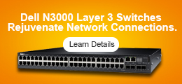
- Коммутаторы Dell Networking N3000
- Коммутаторы HPE 5500 HI
- Коммутаторы HPE 5510 HI
- Коммутаторы HPE FlexFabric 5700
- Коммутаторы HPE FlexFabric 5800
- Коммутаторы HPE FlexFabric 5900
- Коммутаторы HPE FlexFabric 5930
- Коммутаторы HPE FlexFabric 5940
- Коммутаторы HPE FlexNetwork 5120 SI
- Коммутаторы HPE FlexNetwork 5130 HI
- Корпоративные коммутаторы Huawei S6300
- Ethernet-коммутаторы Juniper EX4600
- Корпоративные коммутаторы Huawei S5300
- Корпоративные коммутаторы Huawei S6700
- Базовые и распределительные коммутаторы
- Коммутаторы Cisco Catalyst 9600
- Коммутаторы Aruba 8320
- Cisco Catalyst серии 4500-X
- Cisco Catalyst серии 6500
- Cisco Catalyst серии 6800
- Коммутаторы Cisco Catalyst 9500
- Коммутаторы Cisco Catalyst 4500
- Коммутаторы Dell Networking N4000
- Коммутаторы HPE FlexNetwork 10500
- Коммутаторы Huawei S12700
- Коммутаторы Huawei S7700
- Коммутаторы Huawei S9300
- Коммутаторы Huawei S9700
- Коммутаторы Juniper QFX3000
- Коммутаторы Juniper QFX5100
- Серия базовых коммутаторов D-Link
- Основные коммутаторы H3C
- Коммутаторы для центров обработки данных
- Коммутаторы Cisco Nexus 2000
- Коммутаторы Cisco Nexus 3000
- Коммутаторы Cisco Nexus 5000
- Коммутаторы Cisco Nexus 7000
- Коммутаторы Cisco Nexus 9000
- Коммутаторы ЦОД Huawei CloudEngine 12800
- Коммутаторы ЦОД Huawei CloudEngine 16800
- Коммутаторы ЦОД Huawei CloudEngine 5800
- Коммутаторы ЦОД Huawei CloudEngine 6800
- Коммутаторы для ЦОД Huawei CloudEngine 7800
- Коммутаторы для ЦОД Huawei CloudEngine 8800
- Коммутаторы Dell Networking S4048-ON
- Коммутаторы для центров обработки данных D-Link
- Коммутаторы Dell EMC PowerSwitch серии S 1GbE
- Коммутаторы для экстремальных центров обработки данных
- Промышленные коммутаторы Ethernet
- Коммутаторы агрегации
- Пограничные переключатели
- Коммутаторы Cisco
- коммутатор Cisco Catalyst 9200
- Коммутатор Cisco Catalyst 9300
- Коммутатор Cisco Catalyst 9400
- Коммутатор Cisco Catalyst 9500
- Коммутатор Cisco Catalyst 9600
- Коммутатор Cisco Catalyst 3850
- Коммутатор Cisco Catalyst 3650
- Коммутатор Cisco Catalyst 2960
- Cisco Catalyst 1300 Series Switches
- Микропереключатели Cisco Catalyst
- Компактный коммутатор Cisco Catalyst
- Cisco Nexus серии 3000
- Cisco Nexus серии 5000
- Cisco Nexus серии 9000
- Cisco Nexus серии 7000
- Коммутаторы Cisco Industrial Ethernet 1000
- Защищенные коммутаторы Cisco Catalyst IE3000
- Коммутаторы Cisco Industrial Ethernet 2000
- Коммутаторы Cisco Industrial Ethernet 4000
- Коммутаторы Cisco Industrial Ethernet 5000
- Коммутатор Cisco Catalyst 4500
- Коммутатор Cisco Catalyst 4900
- Коммутатор Cisco Catalyst 6800
- Коммутатор Cisco Catalyst 3560
- Коммутатор Cisco Catalyst 3750
- Коммутатор Cisco Catalyst 6500
- Cisco Nexus серии 2000
- Серия Cisco Catalyst IE9300 Rugged
- Серия Cisco Catalyst IE9311 Rugged
- Серия Cisco Catalyst IE9315 Rugged
- Серия Cisco Catalyst IE9316 Rugged
- Cisco Catalyst серии IE9317 Rugged
- Cisco Catalyst серии IE9318 Rugged
- Серия Cisco Catalyst IE9319 Rugged
- Серия Cisco Catalyst IE9320 Rugged
- Cisco Catalyst серии IE9321 Rugged
- Серия Cisco Catalyst IE9322 Rugged
- Cisco Catalyst серии IE9323 Rugged
- Cisco Catalyst 1200 Series Switches
- Коммутатор Cisco Catalyst 1000
- Adapters
- Cisco Meraki Series Switches
- Cisco Industrial Ethernet 3000 Switches
- Cisco MDS Series Switches
- FC Switches
- Переключатели Аруба
- Переключатели Аруба
- Коммутаторы Aruba серии 8360
- Коммутаторы Aruba серии 8400
- Коммутаторы Aruba серии 2930F
- Коммутаторы Aruba Instant On 1930
- Коммутаторы Aruba серии 2530
- Коммутаторы Aruba серии 2920
- Коммутаторы Aruba серии 3810
- Коммутаторы Aruba серии 2540
- Коммутаторы Aruba серии 2930M
- Коммутаторы Aruba серии 5400R
- Коммутаторы Aruba серии 8320
- Модули коммутатора Aruba v3
- Модули коммутатора Aruba v2
- Aruba переключает трансиверы
- Аксессуары для коммутаторов Aruba
- Коммутаторы Aruba OfficeConnect
- Коммутаторы Aruba 2615
- Коммутаторы Aruba 2620
- Коммутаторы Aruba 2915
- Коммутаторы Aruba серии 6400
- Коммутаторы Aruba серии 6100
- Коммутаторы Aruba серии 6300M
- Коммутаторы Aruba серии 6200F
- Коммутаторы Aruba серии 6000
- Аксессуары для коммутаторов Aruba
- Коммутаторы Aruba серии 6300M
- Коммутаторы Aruba серии 6300F
- Коммутаторы Aruba серии 8320
- HPE Aruba 9300S Series Switches
- Коммутаторы Aruba для центров обработки данных
- Коммутаторы Aruba ProCurve
- Коммутаторы HPE 10500
- Коммутаторы HPE FlexNetwork 5130 EI
- Коммутаторы HPE FlexNetwork 5130 HI
- Коммутаторы HPE FlexNetwork 5120 SI
- Коммутаторы HPE 5500 EI
- Коммутаторы HPE 5500 HI
- Трансиверы Aruba Procurve Switch
- Коммутаторы HPE 5510 HI
- Коммутаторы HPE 3800
- Коммутаторы HPE 3500 и 3500 yl
- Коммутаторы HPE 1950
- Переключатели Aruba 1920
- Коммутаторы Aruba 1900
- Коммутаторы HPE 1820
- Коммутаторы Aruba 1810
- Коммутаторы Aruba 1620
- Коммутаторы HPE 1420
- Коммутаторы Aruba 1410
- Модули HPE 55xx
- Модули коммутации HPE 35xx
- Коммутаторы Aruba 1620
- Коммутаторы Aruba 1900
- Коммутаторы Aruba 1410
- Переключатели Аруба
- Коммутаторы Dell
- Коммутаторы Dell Networking серии X
- Коммутаторы Dell Networking N1500
- Коммутаторы Dell Networking N3000
- Коммутаторы Dell Networking N4000
- Коммутаторы Dell Networking S4048-ON
- Коммутаторы Dell Networking S4100-ON
- Коммутаторы Dell Networking S3000-ON
- Коммутаторы Dell Networking N1000
- Коммутаторы Dell Networking N2000
- КВМ-переключатели Dell
- Dell EMC Networking PowerSwitch серии N2200
- Dell EMC Networking PowerSwitch серии N3200
- Dell EMC PowerSwitch серии N1100
- Коммутаторы Dell EMC PowerSwitch серии S 1GbE
- Переключатели Huawei
- Коммутаторы Huawei серии S1700
- Коммутаторы Huawei серии S2700
- Коммутаторы Huawei серии S3700
- Коммутаторы Huawei серии S5700
- Коммутаторы Huawei серии S5700S
- Коммутаторы Huawei серии S6700
- Коммутаторы Huawei серии S7700
- Коммутаторы Huawei серии S9700
- Коммутаторы Huawei серии S12700
- Коммутаторы для центров обработки данных Huawei
- Коммутаторы Huawei серии S2300
- Коммутаторы Huawei серии S3300
- Коммутаторы Huawei серии S5300
- Коммутаторы Huawei серии S6300
- Коммутаторы Huawei серии S9300
- Коммутаторы для центров обработки данных Huawei
- Huawei S16700 Series Switches
- Huawei S8700 Series Switches
- Переключатели Фортинет
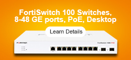
- Fortinet FortiSwitch 100 Series Entry Switches
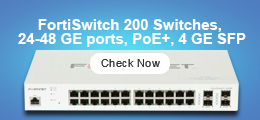
- Fortinet FortiSwitch 200 Series Mid-Range Switches
- Fortinet FortiSwitch 400 Series Premium Switches
- Fortinet FortiSwitch 600 Series Premium Switches
- Fortinet FortiSwitch 1000 Series Premium Switches
- Fortinet FortiSwitch 2000 Series Premium Switches
- Fortinet FortiSwitch 3000 Series Premium Switches
- Fortinet FortiSwitch T1000 Series Premium Switches
- Fortinet FortiSwitch AX3660S Series Premium Switches
- Fortinet FortiSwitch AX2340S Series Premium Switches
- Fortinet FortiSwitch AX2630S Series Premium Switches
- Fortinet FortiSwitch Rugged 400 Series Premium Switches
- Можжевеловые переключатели
- Коммутаторы Ethernet серии Juniper EX4300
- Коммутаторы Ethernet серии Juniper EX2300
- Коммутаторы Ethernet серии Juniper EX4600
- Коммутаторы Ethernet серии Juniper EX3400
- Коммутаторы Ethernet серии Juniper EX3300
- Коммутаторы серии Juniper QFX5200
- Коммутаторы серии Juniper QFX5100
- Коммутаторы серии Juniper QFX3000
- Коммутационные модули и платы Juniper
- Лицензии Juniper Switch
- Коммутаторы Ruckus
- Коммутаторы D-Link
- Интеллектуальные коммутаторы D-Link
- Неуправляемые коммутаторы D-Link
- Полностью управляемые коммутаторы D-Link
- Коммутаторы доступа D-Link
- Коммутаторы агрегации D-Link
- Серия базовых коммутаторов D-Link
- Коммутаторы для центров обработки данных D-Link
- Интеллектуальные коммутаторы управления сетью D-Link
- Промышленные коммутаторы D-Link
- Переключатели точек добавления D-Link
- Проводные сетевые карты D-Link
- Аксессуары для переключателей D-Link
- Ubiquiti переключатели
- Переключатели H3C
- Экстремальные переключатели
- Серия ExtremeSwitching 200
- Серия ExtremeSwitching X440-G2
- Серия ExtremeSwitching X460-G2
- Серия ExtremeSwitching X670-G2
- ExtremeSwitching Серия X695
- ExtremeSwitching Серия VSP 7400
- Коммутаторы Extreme Networks серии A
- Коммутаторы Extreme Networks серии S
- ExtremeSwitching Серия 8000
- Модули и платы Extreme Switches
- Лицензии на коммутаторы Extreme
- Аксессуары для экстремальных переключателей
- Серия Extreme Summit X430
- Переключатели Alcatel-Lucent
- Коммутаторы Микротик
- Переключатели Ариста
- Коммутаторы Arista серии 7050X
- Коммутаторы Arista серии 7010T
- Коммутаторы Arista серии 720XP
- Коммутаторы Arista серии 7150
- Коммутаторы Arista серии 7280R
- Коммутаторы Arista серии 7130
- Коммутаторы Arista серии 7020R
- Коммутаторы Arista серии 7170
- Коммутаторы Arista серии 7160
- Аксессуары для переключателей Arista
- Универсальная платформа для позвоночника Arista 7500R Series
- Ethernet-платформа Arista 7208R Series Universal Leaf
- Переключатели Мелланокс
- Коммутаторы Broadcom
- Ruijie Switches
- MRD Switches
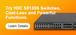
- Переключатели H3C
- MRD
- Arisla Switches
- Brocade Switches
- NVIDIA Mellanox Switches
- NVIDIA Switches
- NVIDIA Quantum InfiniBand Switches
- NVIDIA Spectrum Ethernet Switches
- Брандмауэры
- Cisco ASA серии 5500
- Cisco Firepower серии 1000
- Cisco Firepower серии 2100
- Cisco Firepower серии 4100
- Cisco Firepower серии 7000
- Cisco Firepower серии 8000
- Cisco Firepower серии 9300
- Серия Cisco ISA500
- Устройства Cisco Meraki MX
- Аруба Clearpass
- Серия Fortinet FortiGate NGFW начального уровня
- Fortinet FortiGate NGFW Middle-range Series
- Fortinet FortiGate Rugged Series
- Fortinet FortiWeb Series
- Шлюзы безопасности приложений Huawei
- Брандмауэры центров обработки данных Huawei
- Системы защиты от DDoS-атак Huawei
- Межсетевые экраны нового поколения Huawei
- Платформы безопасности Huawei
- Сервисные шлюзы Juniper SRX
- Межсетевые экраны Cisco
- Cisco ASA серии 5500
- Устройства Cisco Firepower серии 1000
- Устройства Cisco Firepower серии 2100
- Устройства Cisco Firepower серии 4100
- Устройства Cisco Firepower серии 7000
- Устройства Cisco Firepower серии 8000
- Устройства Cisco Firepower серии 9300
- Серия Cisco ISA500
- Аксессуары для устройств Cisco Firepower
- Cisco Firepower 3100 Series Appliances
- Cisco Firepower 4200 Series Appliances
- Cisco Firepower 9000 Series Appliances
- Cisco Secure Web Appliance
- Cisco ISE
- Cisco Secure Endpoint
- Alteon
- Аксессуары для одежды
- Email Security Appliance
- Cisco Firepower 4000 Series Appliances
- Брандмауэры Фортинет
- Платформы сетевой безопасности Fortinet
- Серия Fortinet FortiGate NGFW начального уровня
- Fortinet FortiGate NGFW Middle-range Series
- Fortinet FortiGate NGFW High-end Series
- Fortinet NGFW Licenses
- Fortinet FortiGate Rugged Series
- Fortinet FortiGate/FortiWiFi Series
- Fortinet FortiGate
- FG-7081F-DC-CH
- FG-7081F-CH
- FC-10-FG9H0-660-02-36
- FC-10-FG9H0-660-02-60
- FG-1800F-DC
- Брандмауэры веб-приложений Fortinet FortiWeb
- Централизованные решения Fortinet FortiAnalyzer
- Fortinet UTP License
- Fortinet ATP License
- Fortinet 360 Protection License
- Fortinet Enterprise Protection License
- Fortinet DDoS Protection
- Fortinet Dynamic Application Security Testing
- Fortinet Performance and Breach Attack Simulation
- FortiOS
- Secure Service Edge
- Secure Web Gateway
- Endpoint Agent
- Secure Email Gateway
- Deception Platform
- Digital Risk Protection
- Fortinet Application Delivery Controller
- Платформы сетевой безопасности Fortinet
- Можжевельник безопасности
- Брандмауэры H3C
- Брандмауэры Dell
- Брандмауэры Huawei
- Брандмауэры Sonicwall
- Пало-Альто Брандмауэры
- Межсетевые экраны Palo Alto серии PA-5000
- Межсетевые экраны Palo Alto серии PA-5400
- Межсетевые экраны серии Palo Alto PA-400
- Межсетевые экраны Palo Alto серии PA-3200
- Пало-Альто Брандмауэры нового поколения
- Межсетевые экраны Palo Alto серии PA-5200
- Межсетевые экраны Palo Alto серии PA-800
- Межсетевые экраны Palo Alto серии PA-7000
- Межсетевые экраны Palo Alto серии PA-3000
- Пало-Альто Брандмауэры ION Devices
- Устройство брандмауэров Пало-Альто
- Palo Alto PA-3400 Series Firewalls
- Palo Alto PA-1400 Series Firewalls
- Межсетевые экраны Ubiquiti
- Межсетевые экраны Check Point
- Ruijie Firewalls
- Ruijie Security
- A10 Firewalls
- Hillstone Firewalls
- Hillstone
- Sophos Firewalls
- WatchGuard Firewalls
- Беспроводная связь
- Внутренние точки доступа
- Wi-Fi 6 точек доступа
- Cisco Catalyst 9100 Wi-Fi 6 точек доступа
- Точки доступа Juniper Mist WiFi 6
- Точки доступа HPE Aruba 500H Hospitality WiFi-6
- Точки доступа HPE Aruba 550 WiFi-6
- Точки доступа HPE Aruba 530 WiFi-6
- Точки доступа HPE Aruba 500 WiFi-6
- Точки доступа HPE Aruba серии 510
- Точки доступа Huawei AirEngine WiFi 6
- Fortinet WiFi 6 Access Points
- Точки доступа Ruckus Wi-Fi 6
- Точки доступа H3C Wi-Fi 6
- Экстремальные WiFi 6 точек доступа
- Точки доступа 802.11ac волны 2
- Точки доступа Cisco 1800
- Точки доступа Cisco 2800
- Точки доступа Cisco 3800
- Точки доступа Cisco 4800
- Точки доступа Huawei стандарта 802.11ac Wave 2
- Fortinet 802.11ac Wave 2 Access Points
- Точки доступа Ruckus стандарта 802.11ac Wave 2
- HPE Aruba Instant на точках доступа внутри помещений
- Точки доступа HPE Aruba серии 200
- Точки доступа HPE Aruba серии 300
- Точки доступа H3C 802.11ac
- Экстремальные точки доступа стандарта 802.11ac Wave 2
- Точки доступа Ruckus стандарта 802.11ac Wave 3
- WiFi 7 Access Points
- Wi-Fi 6 точек доступа
- Наружные точки доступа
- Наружные точки доступа Cisco 1560
- Наружные точки доступа Cisco 1570
- Точки доступа Cisco Catalyst серии IW6300 для тяжелых условий эксплуатации
- Наружные точки доступа HPE Aruba 570 WiFi-6
- Точки доступа HPE Aruba 570EX Outdoor WiFi-6
- Точки доступа HPE Aruba 518 повышенной прочности
- Наружные точки доступа Wi-Fi 5 серии Aruba 370
- Наружные точки доступа Wi-Fi 5 серии Aruba 360
- Huawei AirEngine WiFi 6 Наружные точки доступа
- Наружные точки доступа Huawei 8000
- Наружные точки доступа Ruckus
- Уличные точки доступа Ubiquiti
- Cisco Catalyst 9124 WiFi 6 Наружная точка доступа
- Точки удаленного доступа
- Точки доступа SMB
- Контроллеры беспроводной локальной сети
- Контроллеры WLAN — поддержка от 1 до 100 точек доступа
- Контроллеры WLAN — поддержка 101–500 точек доступа
- Контроллеры WLAN — поддержка 501–1500 точек доступа
- Контроллеры WLAN — поддержка 1501–2500 точек доступа
- Контроллеры WLAN — поддержка 2501–6000 точек доступа
- Контроллеры WLAN — поддержка более 6000 точек доступа
- Беспроводные мосты
- Антенны точки доступа
- Беспроводные точки доступа и контроллеры Cisco
- Контроллер беспроводной локальной сети Cisco
- Точка доступа Cisco 1810
- Точка доступа Cisco 1810W
- Точка доступа Cisco 1815
- Точка доступа Cisco 1830
- Точки доступа Cisco 1840
- Точка доступа Cisco 1850
- Точка доступа Cisco 2800
- Точка доступа Cisco 3800
- Точка доступа Cisco 4800
- Точка доступа Cisco Catalyst 9100 Wi-Fi 6
- Точки доступа Cisco Catalyst серии IW6300 для тяжелых условий эксплуатации
- Наружные точки доступа Cisco 1560
- Наружная точка доступа Cisco 1570
- Антенна Cisco 2,4 5 5,8 ГГц
- Точка доступа Cisco 1700
- Точка доступа Cisco 2700
- Точка доступа Cisco 3700
- Точка доступа Cisco 1600
- Точка доступа Cisco 2600
- Точка доступа Cisco 3600
- Сетчатая точка доступа Cisco 1520
- Наружная точка доступа Cisco 1530
- Точка доступа Cisco 1550
- Точка доступа Cisco 3500
- Аксессуары для точки доступа и моста
- Точка доступа Cisco 521
- Точка доступа Cisco 600
- Точка доступа Cisco 700
- Точка доступа Cisco 1130
- Точка доступа Cisco 1140
- Точка доступа Cisco 1240
- Точка доступа Cisco 1250
- Точка доступа Cisco 1260
- Мост точки доступа Cisco 1310
- Точка доступа Cisco 1040
- Мост Cisco серии 1410
- Mobility Services Engine
- Аруба беспроводной
- Точки доступа Арубы
- Aruba Instant на внутренних точках доступа
- Точки доступа Aruba серии 510
- Точки доступа Aruba серии 100
- Точки доступа Aruba серии 200
- Точки доступа Aruba серии 300
- Точки доступа серии Aruba OfficeConnect
- Точки доступа Aruba серии 500
- Точки доступа HPE серии MSM400
- Точки доступа HPE серии 400
- Точки доступа M330
- Антенны точки доступа Aruba
- Точки доступа Aruba 500H Hospitality WiFi-6
- Точки доступа Aruba 550 Wi-Fi-6
- Точки доступа Aruba 530 Wi-Fi-6
- Точки доступа Aruba 500 Wi-Fi-6
- Уличные точки доступа Aruba 570 Wi-Fi-6
- Точки доступа Aruba 570EX Outdoor WiFi-6
- Точка доступа Aruba 518 повышенной прочности
- Точки доступа Aruba 560 Wi-Fi-6
- Аксессуар для точек доступа Aruba
- Другие точки доступа Aruba
- Точки доступа Aruba серии 200
- Точки доступа Aruba серии 100
- Точки доступа Aruba серии 300
- Точки доступа Aruba M330
- Точки доступа серии Aruba OfficeConnect
- Контроллеры Аруба
- Управление безопасностью Арубы
- Лицензии контроллера Aruba
- Лицензии контроллеров Aruba
- Точки доступа Арубы
- Беспроводная связь Huawei
- Fortinet Wireless
- Fortinet FortiAP Access Points
- Fortinet Access Points FortiAP-C24JE
- Fortinet Access Points FortiAP-423E
- Fortinet Access Points FortiAP-421E
- Fortinet Access Points FortiAP-321C
- Fortinet Access Points FortiAP-320C
- Fortinet Access Points FortiAP-224E
- Fortinet Access Points FortiAP-223E
- Fortinet Access Points FortiAP-222E
- Fortinet Access Points FortiAP-221E
- Fortinet FortiAP Access Point Softwares
- Fortinet FortiAP Access Point Accessories
- Fortinet FortiAP Access Points
- Можжевельник беспроводной
- Рукус беспроводной
- Беспроводная связь D-Link
- Ubiquiti Wireless
- Экстремальная беспроводная связь
- Alcatel-Lucent Wireless
- Беспроводная связь H3C
- Беспроводной Микротик
- Ruijie Wireless
- Беспроводные точки доступа Ruckus
- Беспроводная связь Cisco
- Внутренние точки доступа
- Унифицированные коммуникации
- Сетевые аксессуары
- Модули и карты
- Модули и карты Cisco
- Модули коммутатора Cisco Catalyst 9000
- Модули и интерфейсы маршрутизатора Cisco ASR 1000
- Модули и карты межсетевых экранов Cisco
- Маршрутизатор Карты EHWIC WAN
- Маршрутизатор WIC Карты WAN
- Голосовые карты VIC VIC2 VIC3
- Карты маршрутизатора VWIC2 VWIC3
- Сетевые модули NM NME EM
- Голосовые/факсимильные модули PVDM
- Модули AIM маршрутизатора
- Модули ISM маршрутизатора ISR G2 SM
- Модули и карты маршрутизаторов Cisco серии 8000
- Модули коммутатора Cisco 6800
- Модули и карты коммутатора Cisco Nexus 3000
- Модули коммутатора Cisco Nexus 5000
- Модули и карты коммутатора Cisco Nexus 7000
- Модули и карты коммутатора Cisco Nexus 9000
- Модули коммутатора Cisco 4500
- Модули коммутатора Cisco 6500
- Модуль беспроводных услуг Cisco
- Модули Cisco 7200
- Модули Cisco 7600
- Модули и платы коммутатора Cisco IE
- Модули контроллера Cisco
- Модули и платы пограничных платформ Cisco Catalyst серии 8000
- Модули и платы маршрутизатора Cisco ISR 4000
- Модули оптики Cisco
- Память и флэш-память Cisco
- Оптические приемопередатчики Dell
- Трансиверы HPE
- Оптические приемопередатчики Huawei
- Модули и карты Huawei
- Модули и карты маршрутизатора Huawei
- Модуль коммутатора и карты Huawei
- Линейные карты коммутаторов серии S5300
- Линейные карты коммутаторов серии S5700
- Линейные карты коммутаторов серии S7700
- Линейные карты коммутаторов серии S9300
- Линейные карты коммутаторов серии S9700
- Линейные карты коммутаторов серии S12700
- Субкарты коммутатора серии CE8800
- Линейные карты коммутаторов серии CE12800
- Модули безопасности брандмауэра Huawei
- Серверные карты PCIE Huawei
- SSD-карты Huawei PCIe
- Модули и платы коммутаторов Huawei
- Модули и карты маршрутизатора Huawei
- Fortinet Accessories and Transceiver
- Трансиверы Juniper
- Оптические приемопередатчики D-Link
- Везде Модули
- Трансиверы Extreme Networks
- Трансиверы Alcatel-Lucent
- Аксессуары Кингстон
- Сетевые карты Mellanox
- Трансиверы Аруба
- Аксессуары Broadcom
- Аксессуары Intel
- Аксессуары QLOGIC
- ЭМУЛЕКС Аксессуары
- Аксессуары Кингстон
- Ruijie Modules & Cards
- Hillstone Modules & Cards
- Palo Alto Modules & Cards
- NVIDIA BlueField DPUs
- NVIDIA Mellanox Modules
- Модули и карты Cisco
- Блоки питания, кабели и прочее
- Аксессуары для кабелей Cisco
- Блок питания Сиско
- Блок питания коммутатора Catalyst 3650
- Блок питания коммутатора Catalyst 3850
- Блок питания коммутатора Catalyst 9000
- Блок питания коммутатора Catalyst 3560
- Блок питания коммутатора Catalyst 4500
- Блок питания маршрутизатора 800
- Блок питания маршрутизатора ASR
- Блок питания маршрутизатора ISR
- Блок питания коммутаторов Nexus
- Переключатель питания IE
- Источник питания для беспроводных устройств
- Аксессуары Cisco
- Другие продукты Cisco
- Аксессуары HPE
- Аксессуары Dell
- Аксессуары для Huawei
- Аксессуары для маршрутизаторов Huawei
- Аксессуары для коммутаторов Huawei
- Аксессуары для коммутаторов серии S5700
- Аксессуары для коммутаторов серии S5300
- Аксессуары для коммутаторов серии CE8800
- Аксессуары для коммутаторов серии CE7800
- Аксессуары для коммутаторов серии CE6800
- Аксессуары для коммутаторов серии CE5800
- Аксессуары для коммутаторов серии S12700
- Аксессуары для коммутаторов серии S9700
- Аксессуары для коммутаторов серии S9300
- Аксессуары для коммутаторов серии S7700
- Аксессуары для коммутаторов серии S6700
- Аксессуары для коммутаторов серии CE12800
- Аксессуары безопасности брандмауэра Huawei
- Антенны и аксессуары Huawei
- Аксессуары для камер Huawei
- Фортинет Другие
- Унифицированные решения Fortinet FortiSIEM для корреляции событий и управления рисками
- Передовые системы предотвращения угроз Fortinet FortiSandbox
- Решения Fortinet FortiNAC для управления доступом к сети
- Платформы централизованного управления Fortinet FortiManager
- Серверы безопасности обмена сообщениями Fortinet FortiMail
- Серверы управления идентификацией пользователей Fortinet FortiAuthenticator
- Аксессуары Ubiquiti
- Аксессуары для экстремальных сетей
- Extreme Networks Другие продукты
- Другие продукты H3C
- Кабели Mellanox
- Источник питания можжевельника
- Источники питания Аруба
- Аксессуары Аруба
- Аксессуары Мелланокс
- Аксессуары Broadcom
- Ruijie Others
- Ruijie Power Supplies
- H3C Power Supplies, Cables and Other
- Источники питания
- Лицензии Huawei
- Optical Transceivers & Cables
- NVIDIA LinkX® Cables and Transceivers
- Модули и карты
- Серверы
- Стоечные серверы
- Стоечные серверы HPE ProLiant Gen9
- Стоечные серверы HPE ProLiant Gen10
- Серверы HPE ProLiant DL580 Gen10
- Серверы HPE ProLiant DL560 Gen10
- Серверы HPE ProLiant DL388 Gen10
- Серверы HPE ProLiant DL385 Gen10
- Серверы HPE ProLiant DL380 Gen10
- Серверы HPE ProLiant DL360 Gen10
- Серверы HPE ProLiant DL325 Gen10
- Серверы HPE ProLiant DL160 Gen10
- Серверы HPE ProLiant DL20 Gen10
- Серверы HPE ProLiant DL325 Gen10 Plus
- Серверы HPE ProLiant DL385 Gen10 Plus
- Стоечный сервер Dell PowerEdge
- Сервер Dell PowerEdge R740
- Сервер Dell PowerEdge R740xd
- Сервер Dell PowerEdge R640
- Сервер Dell PowerEdge R540
- Сервер Dell PowerEdge R440
- Сервер Dell PowerEdge R340
- Сервер Dell PowerEdge R240
- Сервер Dell PowerEdge R840
- Сервер Dell PowerEdge R940
- Сервер Dell PowerEdge R230
- Сервер Dell PowerEdge R330
- Сервер Dell PowerEdge R430
- Сервер Dell PowerEdge R530
- Сервер Dell PowerEdge R620
- Сервер Dell PowerEdge R630
- Сервер Dell PowerEdge R730
- Сервер Dell PowerEdge R730xd
- Сервер Dell PowerEdge R830
- Сервер Dell PowerEdge R920
- Сервер Dell PowerEdge R930
- Сервер Dell PowerEdge R760
- Сервер Dell PowerEdge R660
- Стоечные серверы Inspur
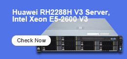
- Стоечные серверы Huawei серии RH
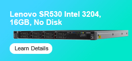
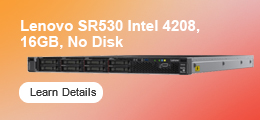
- Стоечные серверы Lenovo
- Стоечные серверы H3C
- Башенные серверы
- Серверы HPE ProLiant Gen9 Tower
- Серверы HPE ProLiant Gen10 Tower
- Серверы Dell PowerEdge Tower
- Серверы Dell PowerEdge T640
- Серверы Dell PowerEdge T440
- Серверы Dell PowerEdge T340
- Серверы Dell PowerEdge T140
- Серверы Dell PowerEdge T30
- Серверы Dell PowerEdge T130
- Серверы Dell PowerEdge T330
- Серверы Dell PowerEdge T430
- Серверы Dell PowerEdge T630
- Серверы Dell PowerEdge T40
- Серверы Dell PowerEdge T150
- Серверы Dell PowerEdge T350
- Серверы Dell PowerEdge T550
- Серверы Inspur Tower
- Серверы Lenovo Tower
- Блейд-серверы
- Серверные системы
- Серверы Процессоры
- Серверы Жесткие диски
- Память сервера
- Серверные аксессуары
- Северные модули и карты
- Серверы Dell
- Сервер Dell в корпусе Tower
- Стоечный сервер Dell
- Сервер Dell PowerEdge R740
- Сервер Dell PowerEdge R740xd
- Сервер Dell PowerEdge R640
- Сервер Dell PowerEdge R750
- Сервер Dell PowerEdge R750xs
- Сервер Dell PowerEdge R750xa
- Сервер Dell PowerEdge R650
- Сервер Dell PowerEdge R550
- Сервер Dell PowerEdge R450
- Сервер Dell PowerEdge R350
- Сервер Dell PowerEdge R250
- Сервер Dell PowerEdge XR11
- Сервер Dell PowerEdge XR12
- Сервер Dell PowerEdge R540
- Сервер Dell PowerEdge R440
- Сервер Dell PowerEdge R340
- Сервер Dell PowerEdge R240
- Сервер Dell PowerEdge R840
- Сервер Dell PowerEdge R940
- Сервер Dell PowerEdge R940xa
- Сервер Dell PowerEdge R6515
- Сервер Dell PowerEdge R6525
- Сервер Dell PowerEdge R7515
- Сервер Dell PowerEdge R7525
- Сервер Dell PowerEdge R230
- Сервер Dell PowerEdge R330
- Сервер Dell PowerEdge R430
- Сервер Dell PowerEdge R530
- Сервер Dell PowerEdge R620
- Сервер Dell PowerEdge R630
- Сервер Dell PowerEdge R730
- Сервер Dell PowerEdge R730xd
- Сервер Dell PowerEdge R830
- Сервер Dell PowerEdge R920
- Сервер Dell PowerEdge R930
- Сервер Dell PowerEdge R760
- Сервер Dell PowerEdge R660
- Серверные модули и карты Dell
- ИИ-серверы Dell
- Dell Rack Servers
- Серверы Huawei
- Серверы Lenovo
- Стоечные серверы Lenovo
- Стоечные серверы Lenovo ThinkSystem SR570
- Стоечные серверы Lenovo ThinkSystem SR530
- Стоечные серверы Lenovo ThinkSystem SR550
- Стоечные серверы Lenovo ThinkSystem SR590
- Стоечные серверы Lenovo ThinkSystem SR650
- Стоечные серверы Lenovo ThinkSystem SR850
- Стоечные серверы Lenovo ThinkSystem SR860
- Стоечные серверы Lenovo ThinkSystem SR258
- Стоечные серверы Lenovo ThinkSystem SR588
- Серверы Lenovo Tower
- Жесткие диски сервера Lenovo
- Память сервера Lenovo
- Серверные блоки питания Lenovo
- Карты серверного массива Lenovo
- Сетевые карты сервера Lenovo
- Серверные HBA-карты Lenovo
- Гибридные флэш-массивы Lenovo Server
- Аксессуары для серверных хранилищ Lenovo
- Lenovo Rack Servers
- Lenovo AI Servers
- Lenovo Rack Server
- Стоечные серверы Lenovo
- Серверы H3C
- Серверы Inspur
- Серверы HPE
- Стоечные серверы HPE
- Серверы HPE ProLiant DL580 Gen9/10
- Серверы HPE ProLiant DL560 Gen9/10
- Серверы HPE ProLiant DL388 Gen9/10
- Серверы HPE ProLiant DL385 Gen10
- Серверы HPE ProLiant DL380 Gen10
- Серверы HPE ProLiant DL385 Gen10 Plus
- Серверы HPE ProLiant DL360 Gen9/10
- Серверы HPE ProLiant DL325 Gen10
- Серверы HPE ProLiant DL325 Gen10 Plus
- Серверы HPE ProLiant DL180 Gen9
- Серверы HPE ProLiant DL160 Gen9/10
- Серверы HPE ProLiant DL120 Gen9
- Серверы HPE ProLiant DL20 Gen9/10
- Серверы HPE ProLiant DL360 Gen10 Plus
- Серверы HPE ProLiant DL380 Gen10 Plus
- HPE ProLiant DL20 Gen9
- Серверы HPE в корпусе Tower
- Блейд-серверы HPE
- Вычислительные модули HPE Synergy 480 Gen10
- Вычислительные модули HPE Synergy 660 Gen10
- Корпус HPE Synergy 12000
- Варианты электропитания корпуса HPE Synergy 12000
- Сетевые модули ввода-вывода блейд-сервера HPE
- Блейд-сервер HPE ProLiant BL660c
- Блейд-сервер HPE ProLiant BL460c
- Блейд-сервер HPE ProLiant BL920s
- Блейд-система HPE c3000
- Блейд-система HPE c7000
- Графический блейд-сервер HPE ProLiant WS460c
- Мезонинная плата/сеть блейд-сервера HPE
- Серверы HPE Apollo
- Серверы HPE Apollo r2200
- Серверы HPE Apollo r2600
- Серверы HPE Apollo r2800
- Серверы HPE Apollo 4200
- Серверы HPE Apollo 4510
- Серверы HPE Apollo 4520
- Серверы HPE Apollo 4530
- Серверы HPE Apollo 6000
- Серверы HPE Apollo k6000
- Серверы HPE Apollo d6500
- Серверы HPE ProLiant XL170r
- Серверы HPE ProLiant XL190r
- Серверы HPE ProLiant XL230k
- Серверы HPE ProLiant XL450
- Серверные процессоры HPE
- Серверные процессоры HPE DL20
- Серверные процессоры HPE DL120
- Серверные процессоры HPE DL160
- Серверные процессоры HPE DL180
- Серверные процессоры HPE DL360
- Серверные процессоры HPE DL380
- Серверные процессоры HPE DL385
- Серверные процессоры HPE DL560
- Серверные процессоры HPE DL580
- Серверные процессоры HPE ML30
- Серверные процессоры HPE ML110
- Серверные процессоры HPE ML150
- Серверные процессоры HPE ML350
- Блейд-серверные процессоры HPE BL460c
- Блейд-серверные процессоры HPE BL660c
- Серверы HPE Apollo Процессоры
- Серверные процессоры HPE DL380
- Жесткие диски для серверов HPE
- Память сервера HPE
- Сетевые контроллеры серверов HPE
- Контроллеры серверных хранилищ HPE
- Серверные лицензии HPE
- Сетевые карты сервера HPE
- Серверные блоки питания HPE
- Аксессуары для серверов HPE
- HPE AI Servers
- HPE Rack Server
- Стоечные серверы HPE
- Серверы Juniper
- Балансировщики нагрузки F5
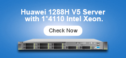
- серверы xFusion
- Стоечный сервер FusionServer 1288H V5
- Стоечный сервер FusionServer 1288H V6
- Стоечный сервер FusionServer 2288H V5
- Стоечный сервер FusionServer 2288H V6
- Стоечный сервер FusionServer 2488H V5
- Стоечный сервер FusionServer 2488H V6
- Стоечный сервер FusionServer 5288H V5
- Стоечный сервер FusionServer 5288H V6
- Стоечный сервер FusionServer 5885H V5
- Сервер FusionServer CX5200 V5
- Стоечный сервер
- Supermicro Servers
- Cisco Servers
- Kits
- ASUS Servers
- AI Server
- HPE STORAGES
- SuperMicr Servers
- NVIDIA ConnectX NICs and SuperNICs
- NVIDIA BlueField Data Processing Units (DPUs)
- Стоечные серверы
- Хранилища
- Хранилища с прямым подключением DAS
- Сетевые хранилища NAS
- Сеть хранения данных Хранилища SAN
- Гибридные флэш-накопители
- Хранилища SAN/DAS/NAS
- Другие хранилища
- Переключатели/контроллеры хранения
- Трансиверы/модули/карты хранения
- Лицензии на хранение
- СХД HPE
- Хранилища HPE MSA
- Коммутаторы сети хранения данных HPE
- Трансиверы системы хранения данных HPE
- Система хранения HPE 3PAR
- Ленточные хранилища HPE StoreEver
- Дисковые полки HPE
- Ленточные хранилища HPE
- Хранилища HPE NAS StoreEasy
- HPE StoreВиртуальные хранилища
- Хранилища HPE StoreOnce
- HPE Nimble Storage
- Лицензии на системы хранения данных HPE
- Ленточные хранилища HPE
- Склады Инспур
- Хранилища Dell
- Система хранения Huawei
- Хранилища Synology
- Хранилища QNAP
- Hitachi Storages
- Lenovo Storages
- NetApp Storages
- Kioxia Storages
- Samsung Storages
- Solidigm Storages
- Intel Storages
- Видеонаблюдение
- IP-камеры
- Цифровые видеомагнитофоны
- Сетевые видеорегистраторы
- PTZ-камеры
- Видеонаблюдение Дахуа
- IP-камеры Дахуа
- 1-мегапиксельные IP-камеры Dahua
- 1,3-мегапиксельные IP-камеры Dahua
- 2-мегапиксельные IP-камеры Dahua
- 3-мегапиксельные IP-камеры Dahua
- IP-камеры Dahua 4MP
- IP-камеры Dahua 4K
- 5-мегапиксельные IP-камеры Dahua
- 6-мегапиксельные IP-камеры Dahua
- 8-мегапиксельные IP-камеры Dahua
- 12-мегапиксельные IP-камеры Dahua
- Несколько IP-камер ePoE
- Видеорегистратор Дахуа
- 4-канальный сетевой видеорегистратор Dahua
- 8-канальный сетевой видеорегистратор Dahua
- 16-канальный сетевой видеорегистратор Dahua
- 24-канальный сетевой видеорегистратор Dahua
- 32-канальный сетевой видеорегистратор Dahua
- 64-канальный сетевой видеорегистратор Dahua
- 128-канальный сетевой видеорегистратор Dahua
- 256-канальный видеорегистратор Dahua
- Дахуа XVR
- Дахуа CVI
- Дахуа PTZ
- Видеорегистратор Дахуа
- Сетевые видеосерверы Dahua
- Хранилища Дахуа
- Контроль доступа Дахуа
- Сигнализация Дахуа
- Эксклюзивные продукты проекта Dahua
- Дисплей и управление Dahua
- Dahua Mobile и трафик
- Трансмиссия Дахуа
- Видеодомофоны Dahua
- Другие продукты Дахуа
- IP-камеры Дахуа
- Видеонаблюдение Hikvision
- Сетевые камеры Hikvision
- Сетевые камеры Hikvision серии IP
- Сетевые камеры Hikvision серии PanoVu
- Сетевые камеры серии Hikvision DeepinView
- Взрывозащищенные сетевые камеры Hikvision серии
- Сетевые камеры Hikvision Anti-Corrosion Series
- Сетевые камеры Hikvision серии AcuSense
- Сетевые камеры специальной серии Hikvision
- Сетевые камеры серии Hikvision Pro (EasyIP)
- Сетевые камеры серии Hikvision ColorVu
- Панорамные сетевые камеры Hikvision серии
- Сетевые камеры серии Hikvision Ultra (SmartIP)
- Сетевые камеры Hikvision серии Wi-Fi
- Камеры Hikvision Turbo HD
- Аналоговые камеры Hikvision
- Цифровые видеорегистраторы Hikvision
- Сетевые видеорегистраторы Hikvision
- Hikvision NVR серии 7600
- Hikvision NVR серии 7700
- Hikvision NVR серии 8600
- Hikvision NVR серии 9600
- Сетевой видеорегистратор серии Hikvision AcuSense
- Сетевой видеорегистратор серии Hikvision Ultra
- Видеорегистратор Hikvision серии Value
- Сетевой видеорегистратор серии Hikvision DeepinMind
- NVR специальной серии Hikvision
- Сетевой видеорегистратор серии Hikvision Pro
- Hikvision PTZ
- Тепловизионные камеры Hikvision
- Видеодомофон Hikvision
- Hikvision Контроль доступа
- Продукция Hikvision HiLook
- Мобильные продукты Hikvision
- Интеллектуальные продукты Hikvision для дорожного движения
- Продукция Hikvision для передачи и отображения
- Сигнализация Hikvision
- Hikvision Другие продукты
- Сетевые камеры Hikvision
- Видеонаблюдение Хуавей
- Аксессуары для видеонаблюдения
- Оптическая сеть доступа
- Оптическая сеть передачи
- Потребитель
- Телефоны и аксессуары
- Сеть
- 5G-маршрутизаторы
- 5G-маршрутизаторы Huawei
- 5G-маршрутизаторы ZTE
- 5G-маршрутизаторы Сяоми
- Маршрутизаторы OPPO 5G
- Маршрутизаторы China Unicom 5G
- 5G-маршрутизаторы D-Link
- Маршрутизаторы Netgear 5G
- Маршрутизаторы Linksys 5G
- Мобильный Wi-Fi 5G
- Аксессуары для маршрутизатора 5G
- Маршрутизаторы TCL/Alcatel 5G
- 5G-маршрутизаторы Zyxel
- Маршрутизаторы Verizon 5G
- 5G-маршрутизаторы Nokia
- Подумайте о маршрутизаторах 5G
- 5G-маршрутизаторы Hongdian
- 5G-модули
- 4G-маршрутизаторы
- Wi-Fi роутеры
- Wi-Fi маршрутизаторы ASUS
- WiFi-маршрутизаторы Huawei
- Wi-Fi роутеры Сяоми
- WiFi-маршрутизаторы Netgear
- Мобильные маршрутизаторы Netgear
- Wi-Fi роутеры TP-Link
- Мобильные беспроводные маршрутизаторы TP-Link
- Домашние Wi-Fi роутеры UBNT
- Гугл WiFi роутеры
- Wi-Fi маршрутизаторы Микротик
- Wi-Fi роутеры Tenda
- Ruijie WiFi Routers
- Wi-Fi системы
- Точка доступа Wi-Fi/удлинитель/спутник
- Переключатели
- Камеры
- 5G-маршрутизаторы
- Компьютеры и офис
- Проекторы
- Ноутбуки
- Настольные компьютеры
- Настольные компьютеры Dell 3967M
- Настольные компьютеры Dell 3046 MT
- Настольные компьютеры Dell 3050 MT
- Настольные компьютеры Dell 5050 MT
- Настольные компьютеры Dell 7050 MT
- Настольные компьютеры Dell Alienware
- Настольные компьютеры Dell Vostro
- Моноблок Dell Inspiron «все в одном»
- Настольный компьютер Dell OptiPlex
- HPE OMEN для настольных ПК
- Игровой настольный компьютер HPE Paviling
- Тонкий настольный ПК HPE
- Настольные компьютеры Dell
- Настольные компьютеры Dell 3967M
- Настольные компьютеры Dell 3046 MT
- Настольные компьютеры Dell 3050 MT
- Настольные компьютеры Dell 5050 MT
- Настольные компьютеры Dell 7050 MT
- Настольные компьютеры Dell Alienware
- Настольные компьютеры Dell Vostro
- Моноблок Dell Inspiron «все в одном»
- Настольный компьютер Dell OptiPlex
- Настольные компьютеры HPE
- Рабочие станции
- Мониторы
- Колодки
- Ноутбуки
- Видеокарты
- Умные устройства
- 5G-устройства
- Потребитель Huawei
- ZTE Потребитель
- Более дешевый выбор
- Телефоны и аксессуары
- Микротик
- Палатка
- Соникволл
- Кингстон
- Ость
- Высокий полюс
- Вездесущий
- Мелланокс
- шум
- Аруба
- Network Management
- Fortinet Network Management
- Fortinet Secure Network Access Control
- Central Management
- Multi-tenant Portal
- Artificial Intelligence for IT Operations
- Endpoint Detection and Response
- Security Information and Event Management
- Security Orchestration, Automation, and Response
- Privileged Access Management
- Identity and Access Management
- Security Fabric Analytics
- Sandbox Analysis
- Network Detection and Response
- Security Orchestration
- Cisco Network Management
- Fortinet Network Management
- Swtiches
- Cyber Security
- Безопасноть
- Ruijie
- Power supply
- Другие
- controller
- Беспроводная связь H3C
- Power Supplies
- H3C
- Hillstone
- xFusion
- A10
- F5
- Palo Alto
- Check Point
- Supermicro
- Data Protection
- ASUS
- AI Workstation
- AI Accelerators
- Data Center Switches
- Сетевые лицензии
- NVIDIA
Search
Логин