


When a network engineer configures a Juniper MX204 QSFP28 port for 10G breakout mode while the adjacent port in the same hardware group remains configured for 100G operation, the Packet Forwarding Engine (PFE) may generate a Rate-Select Port Grouping Mismatch and trigger %PFE-3-ERR messages. This behavior is not a software bug. It is a hardware-level limitation of the MX204's Eagle Trio ASIC architecture, where adjacent ports share a common PLL (Phase-Locked Loop) clock source. Ports within the same group must operate within compatible SerDes clock families, and after modifying port speed configurations, an FPC restart is often required before the new hardware clock settings become active.
- Interface remains Link-Down after a successful commit, breakout interfaces fail to appear, and continuous %PFE-3-ERR messages occur in system logs.
- The hardware model division into physical port groups sharing SerDes resources, PLL clock circuitry, and ASIC synchronization mechanisms.
- Deep dive into the 25G-based clock family vs. the 10G-based clock family and how clock mismatch prevents successful hardware lock.
- Decoding the log strings for rate-select mismatches and analyzing PIC Mode vs. Port Mode speed profiles.
- Valid configuration scenarios including 4x10G breakout deployment, 100G and 25G coexistence, and data center edge designs.
- Step-by-step recovery using FPC/PIC restart commands and lower-level PFE shell diagnostics to investigate synchronization issues.
- Risk reduction steps during production, lifecycle management considerations, and answers to common troubleshooting questions.
Common MX204 Rate-Select Port Grouping Mismatch Symptoms
Most engineers encounter this issue during 4x10G breakout deployments, 100G-to-10G migration projects, data center edge upgrades, WAN aggregation redesigns, or port speed reconfiguration during maintenance windows.
Common symptoms include interfaces remaining Link-Down after a successful commit, breakout interfaces failing to appear, or adjacent QSFP28 ports unexpectedly going offline. You may also observe continuous %PFE-3-ERR messages in system logs, port initialization failures after changing speed settings, or hardware alarms related to rate selection and PLL synchronization.
A typical scenario looks like this: when configuring set chassis fpc 0 pic 0 port 0 speed 10g, the commit succeeds, but et-0/0/0 remains down, et-0/0/1 unexpectedly drops, and PFE logs report port-group errors. If this behavior sounds familiar, the issue is usually related to a port-group clock conflict rather than a failed optic or faulty cable.
Understanding the MX204 Port Group Architecture
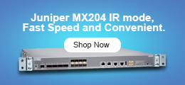
The MX204 contains four front-panel QSFP28 interfaces and is built on Juniper's compact 1RU edge routing architecture. Although this article focuses on troubleshooting rate-select port grouping conflicts, understanding the underlying hardware model is important when planning breakout deployments, optics selection, or capacity upgrades. The Juniper MX204-HW-BASE remains a widely deployed platform for service provider edge, enterprise WAN, and data center interconnect environments due to its high throughput, port density, and power efficiency.
Internally, the ports are divided into two physical groups within PIC 0:
- Port Group 0: Port 0 (et-0/0/0) and Port 1 (et-0/0/1)
- Port Group 1: Port 2 (et-0/0/2) and Port 3 (et-0/0/3)
Each port group shares SerDes resources, PLL clock circuitry, hardware lane initialization logic, and ASIC synchronization mechanisms. Because of these shared resources, ports within the same group cannot always operate independently.
Why MX204 Ports Must Share the Same Speed Family
The root cause of most rate-select errors is the MX204's shared PLL architecture. Each port group can lock to only one SerDes clock family at a time:
- 25G-Based Clock Family (Clock rate: 25.78125 Gbps): Used by 100GbE, 25GbE, and 4x25GbE breakout modes.
- 10G-Based Clock Family (Clock rate: 10.3125 Gbps): Used by 40GbE, 10GbE, and 4x10GbE breakout modes.
A conflict occurs when adjacent ports require different clock families. For example, if you configure set chassis fpc 0 pic 0 port 0 speed 10g while Port 1 remains configured as 100G, the hardware attempts to drive Port 0 at 10.3125 Gbps and Port 1 at 25.78125 Gbps simultaneously. Because both ports share the same PLL, the clock cannot lock successfully, causing hardware initialization to fail.
Check stock, compare options, or talk with our team.
Common Junos %PFE-3-ERR Errors and Their Meaning
When a speed-family conflict occurs, the MX204 often generates messages similar to the following system log alerts:
Additional errors may include PCS initialization failed, port group verification failed, rate-select mismatch detected, or hardware lane initialization failed. These messages are valuable because they point directly to the underlying clock constraints.
PIC Mode vs Port Mode Explained
Another source of configuration divergence is the difference between PIC Mode and Port Mode:
- PIC Mode: All ports within the PIC operate under a common speed profile. This provides simpler administration, predictable behavior, and easier troubleshooting, but limits deployment flexibility due to uniform speed requirements.
- Port Mode: Allows individual port speed assignments (e.g., setting Port 0 to 10G, Port 1 to 40G, Port 2 to 100G, and Port 3 to 25G). While Port Mode increases deployment flexibility, it does not eliminate the hardware-level clock-group restrictions shared by adjacent ports.
Supported MX204 Port Speed Configuration Examples
To plan your layouts without triggering conflicts, check these valid deployment profiles:
Scenario 1: 4x10G Breakout Deployment
If Port 0 is configured for 10G breakout, Port 1 must remain within the same 10G-based clock family. Valid configurations include:
Alternatively, pairing 10G and 40G is fully functional:
Result: The PLL synchronizes smoothly, the port group initializes, and no PFE errors are thrown.
Scenario 2: 100G and 25G Coexistence
Both speeds belong to the 25G clock family, meaning they can safely reside in the same group:
Result: The shared PLL remains compatible, and the port group becomes fully operational without rate-select conflicts.
Scenario 3: Data Center Edge Design
A common optimization topology that maximizes interface density while maintaining clock-family compatibility across both groups:
- Group 0 (10G Family): Port 0 = 4x10G breakout / Port 1 = 40G aggregation uplink
- Group 1 (25G Family): Port 2 = 100G core uplink / Port 3 = 4x25G server connectivity
Why MX204 Interfaces Stay Down After a Successful Commit
Many engineers assume that a successful commit means the hardware has accepted the change. However, MX204 hardware clocking behaves differently. Following a commit, interfaces may remain down because PLL settings are initialized during hardware startup, and SerDes parameters are loaded during PIC/FPC initialization. Hardware clock synchronization does not automatically reload after every commit, meaning the software configuration updates successfully while the hardware continues using the previous clock state.
How to Apply Port Speed Changes Correctly
After modifying port speed configurations, restart the hardware resources responsible for clock initialization. The recommended command is:
This forces an FPC reboot, microcode reload, PLL reinitialization, SerDes synchronization, port group validation, and eventual interface recovery. Alternatively, you can bounce the individual PIC:
Always schedule a maintenance window for these steps because traffic interruption is expected during the reload cycle.
Advanced PFE Diagnostics for MX204 Port Group Issues
When standard interface commands are insufficient, deeper diagnostics can reveal the actual hardware state. Run standard interface health checks via show interfaces terse or show interfaces extensive et-0/0/0 to check physical status, PCS state, FEC status, and lane synchronization.
To view low-level port operational information directly from the forwarding hardware, use:
This reveals the active port state, hardware lane mapping, SerDes initialization status, and clock-group assignment. To review PFE system logs for specific clock failures, run:
For advanced real-time debugging, access the PFE shell using start shell pfe network fpc0 and inspect error counts via show pfe statistics error to separate configuration layout mismatches from true physical hardware failures.
MX204 Deployment Best Practices
- Document port-group dependencies before implementation.
- Avoid mixing 10G/40G and 25G/100G clock families within the same port group.
- Validate breakout requirements before ordering optics or breakout cables.
- Lab-test port speed modifications whenever possible before staging production.
- Schedule proper maintenance windows for clock-family modifications and restart the PIC or FPC after major changes.
- Verify hardware synchronization via PFE tools before returning services to production status.
Optics Planning and Lifecycle Considerations
Port-group limitations directly influence optics and cabling decisions. Before purchasing 100G QSFP28 optics, 40G QSFP+ modules, 4x10G breakout DACs, or 4x25G breakout cables, network teams must verify how planned speeds align across the MX204 port groups. For organizations extending the lifecycle of existing deployments, the platform's constraints are easily managed with upfront layout design.
| Platform Variant | Form Factor | Port Breakdown | Primary Deployment Applications |
|---|---|---|---|
| Juniper MX204-HW-BASE | 1RU Compact | 4x QSFP28 (Ports 0-3) & 8x SFP+ Fixed | Service Provider Edge, Enterprise WAN, Data Center Interconnect (DCI) |
People Also Ask (FAQ)
The Junos software validation process confirms the configuration syntax is correct and saves it to the database. However, physical hardware clocking elements like PLL and SerDes profiles are only initialized during boot or restart events, requiring manual intervention to reload the hardware state.
In most cases involving clock-family changes (e.g., switching from 100G to 10G breakouts), yes. Restarting the FPC via request chassis fpc slot 0 restart or taking the PIC offline and online is required to load the new microcode configuration parameters and sync physical lanes.
Yes. Both 25G and 100G configurations utilize the same base SerDes clock lane frequency family (25.78125 Gbps). Because the shared PLL can successfully lock onto this single clock family rate, they can coexist without causing errors.
The 4 fixed QSFP28 ports are divided into two pairs: Port 0 (et-0/0/0) and Port 1 (et-0/0/1) form Port Group 0, while Port 2 (et-0/0/2) and Port 3 (et-0/0/3) form Port Group 1.
The error is thrown when ports residing within the exact same group are concurrently configured for mismatched clocking profiles (10G/40G family vs. 25G/100G family), which breaks the shared PLL lock loop capabilities of the Eagle Trio ASIC.