OLT Capacity Planning for GPON Access NetworksPlan OLT capacity for GPON OLT systems and EA5800 capacity planning, optimizing GPON split ratio and OLT uplink design for scalable fiber access.
Enterprise OLT Platform Selection for Fiber AccessDesign enterprise OLT platform strategy for GPON OLT platform, modular OLT chassis, and OLT service boards to scale passive optical LAN and XG-PON evolution.
Tunnel Video Surveillance VLAN Stability over FiberDesign stable tunnel video surveillance VLANs using optical transport backbone and Arista fiber aggregation for resilient Huawei OptiX OSN CCTV networks.
Fiber vs Copper in Industrial Networks Design GuideCompare fiber vs copper in industrial ethernet, plan hybrid industrial fiber network designs, and select rugged ethernet switches and industrial SFP transceivers.
You are executing a rolling upgrade of 48 high-density Wi-Fi 6E/7 Access Points (APs) and smart building IoT sensors on a Friday night. Suddenly, as the third stack member reboots, half of the newly connected APs fail to power up, throwing %ILPOWER-3-CONTROLLER_PORT_ERR and %PLATFORM_ENV-1-PWR_FAIL errors across your syslog server. This is the classic symptom of an under-provisioned power budget.
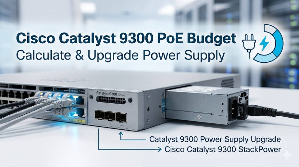
Calculating the Cisco Catalyst 9300 PoE Budget and planning a Catalyst 9300 Power Supply Upgrade requires a deep understanding of hardware power allocation, ASIC-level power management, and the mechanics of Cisco Catalyst 9300 StackPower. This guide provides the exact mathematical formulas, hardware specifications, and CLI commands needed to design a resilient power architecture for your enterprise network.
Part 1: Architectural and ASIC Overview of Catalyst 9300 Power Delivery
The Cisco Catalyst 9300 Series is built on the Unified Access Data Plane (UADP) 2.0/3.0 ASIC architecture. While the ASIC handles line-rate packet forwarding, a dedicated onboard Power Management Microcontroller (MCU) communicates with the Power Supply Units (PSUs) and PoE controller chipsets via an internal I2C/SMBus control plane.
When a Powered Device (PD) is connected to an RJ45 or Multigigabit (mGig) port, the physical layer PoE controller detects the device's signature resistance. The switch then allocates power based on the negotiated class (IEEE 802.3af, 802.3at PoE+, 802.3bt UPOE/UPOE+).
To ensure uninterrupted packet delivery, the UADP ASIC pipeline is decoupled from the PoE power plane. However, if the total power draw exceeds the physical capacity of the installed PSUs, the PoE controller will shut down ports based on configured priorities to protect the switch's core control plane.
By utilizing Cisco Catalyst 9300 StackPower technology, network engineers can pool the power resources of up to four switches in a single stack ring (or up to eight switches using an external eXpandable Power System XPS-2200). This architectural feature creates a single, virtualized power pool. If a single PSU fails, the remaining PSUs in the stack dynamically redistribute power to prevent port flapping and system reboots.
To design a stable power architecture, you must first select the appropriate switch chassis. You can explore the Cisco Catalyst 9300 Series Switches Portfolio to evaluate the physical port configurations and default power options available for your deployment.
Part 2: Hardware Specifications and Performance Sizing Guide
Calculating the available Cisco Catalyst 9300 PoE Budget requires subtracting the switch's internal system power consumption from the total power output of the installed PSUs.
The Mathematical Formula for PoE Budgeting
Available PoE Budget = Sum of PSU Output Power - Switch System Power Draw
Note: Switch system power draw varies by model. A standard 48-port copper switch (e.g., C9300-48P) consumes approximately 85W to 100W for its own internal circuitry, fans, and ASIC operations.
Power Supply Unit (PSU) Matrix
The Catalyst 9300 platform supports hot-swappable, redundant power supplies. The table below outlines the power output and PoE capabilities of the primary AC power supply options:
PSU Model
Total Output Power
System Power Allocation
Max PoE Budget (Single PSU)
Max PoE Budget (Dual PSUs)
PWR-C1-350WAC-P
350W
~100W
250W
600W
PWR-C1-715WAC-P
715W
~110W
605W
1320W
PWR-C1-1100WAC-P
1100W
~110W
990W
1980W (Full 48-port PoE+)
PWR-C1-1900WAC-P
1900W
~150W
1750W
3370W (Full 48-port UPOE+)
Executing a Catalyst 9300 Power Supply Upgrade
When upgrading your network to support high-power devices like Wi-Fi 6E APs (which require IEEE 802.3at Class 4 or 802.3bt Class 5 power), you must verify your current power allocation and configure the switch to handle the new load.
Use the following CLI commands to verify your current power configuration, check for PoE drops, and configure Cisco Catalyst 9300 StackPower for optimal redundancy:
# Step 1: Verify the current power supplies and operational status
show platform software power-manager switch 1

# Step 2: Check the real-time PoE consumption and remaining budget
show power inline

# Step 3: Configure StackPower in Power Sharing mode for maximum budget allocation
configure terminal
 stack-power stack Power-Pool-1
  mode power-sharing
  no strict
  exit
!
interface range GigabitEthernet1/0/1 - 48
 # Step 4: Set static PoE allocation on critical ports to prevent dynamic negotiation drops
 power inline consumption static 30000
 end

# Step 5: Verify the StackPower distribution across the stack
show stack-power detail
By setting the StackPower mode to power-sharing with the no strict parameter, the switch stack pools all available power from all installed PSUs. This configuration allows the stack to dynamically allocate power where it is needed most, preventing localized PoE budget exhaustion on individual switches.
Part 3: Sourcing, BOM Optimization, and Risk Mitigation
When planning a large-scale hardware refresh or a Catalyst 9300 Power Supply Upgrade, procurement delays can stall critical project timelines. Traditional distribution channels often quote lead times of 6 to 8 weeks for Cisco power supplies and switches, which can lead to project delays and increased overhead.
Router-switch addresses these supply chain challenges by maintaining over $20 million in on-shelf inventory across multiple global warehouses. This extensive stock allows for same-week dispatch on critical components, including PWR-C1-1100WAC-P and PWR-C1-1900WAC-P power supplies. By operating a streamlined, flat supply chain, Router-switch bypasses multiple layers of regional distributor markups, allowing system integrators and enterprise IT departments to secure direct bulk-purchase discounts.
To ensure long-term reliability and mitigate post-deployment risks, Router-switch provides comprehensive hardware protection:
100% Genuine Guarantee: Every Cisco Catalyst 9300 switch and power supply shipped features fully verifiable serial numbers (S/N) that can be validated directly in Cisco's official databases.
Complimentary 3-Year RS Care Warranty: This extended warranty provides robust hardware protection, offering an alternative to costly annual support contracts.
Rapid RMA Standby Replacement: In the rare event of a hardware failure, Router-switch ships a replacement unit first to minimize your Mean Time to Resolution (MTTR) and keep your network running smoothly.
Expert Engineering Support: Access free, 1-on-1 CCIE-level technical consultancy to assist with BOM optimization, StackPower design, and power budget calculations.
To integrate these power-optimized switches into your broader infrastructure, you can browse the Cisco Switches Solutions Catalog to find compatible hardware and accessories for your deployment.
Part 4: Frequently Asked Questions (FAQ)
Q1: Can I mix different power supply models (e.g., a 715W and an 1100W) in a single Catalyst 9300 switch?
Yes. The Catalyst 9300 supports mixing different AC power supply units within the same chassis. The switch's power management controller will combine their outputs to determine the total available Cisco Catalyst 9300 PoE Budget. However, for optimal power efficiency and balanced thermal dissipation, Cisco recommends using matching PSU models whenever possible.
Q2: What is the difference between the older PWR-C1-1100WAC and the newer PWR-C1-1100WAC-P power supplies?
The "-P" suffix denotes Platinum-rated power efficiency. The PWR-C1-1100WAC-P offers higher power conversion efficiency (up to 94%) compared to the older Gold-rated PWR-C1-1100WAC. This improved efficiency reduces heat generation and lowers overall power consumption in high-density data closets. Both models are fully backward compatible and can be used for a Catalyst 9300 Power Supply Upgrade.
Q3: How does Cisco Catalyst 9300 StackPower handle a power supply failure in redundant mode?
When configured in Redundant Mode (either N+1 or Multi-Chassis Redundant), Cisco Catalyst 9300 StackPower reserves the capacity of the largest PSU in the pool as a backup. If one of the active PSUs fails, the reserved power is instantly distributed across the stack ring. This transition occurs within microseconds, preventing switch reboots and ensuring that connected PoE devices do not lose power.
Q4: Why does my switch show a "Power-I-C" or "faulty" status after installing a new 1900W power supply?
This issue typically occurs when a high-power PSU, such as the PWR-C1-1900WAC-P, is installed in an older Catalyst 9300 chassis that is running outdated Cisco IOS-XE software. The 1900W PSU requires Cisco IOS-XE 17.3.1 or later to be properly recognized by the system. Upgrading your switch's software image will resolve this detection issue and enable the full power budget.
Expertise Builds Trust
20+ Years • 200+ Countries • 21500+ Customers/Projects CCIE · JNCIE · NSE7 · ACDX · HPE Master ASE · Dell Server/AI Expert